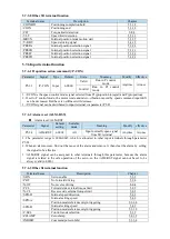
5.7.5.4 Warn output (/WARN)
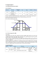
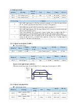
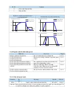
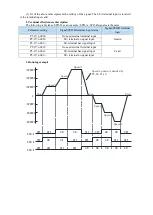
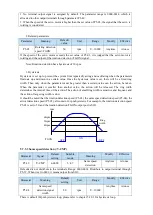
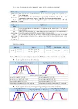
Set the alarm output threshold, when the current speed is higher than the warning speed, output /
WARN.
Parameter
Meaning
Default
value
Unit
Range
Modify
Effective
P3-19
Forward warning
speed
Motor
related
rpm
0
~
65535
Servo bb
At once
P3-20
Reverse warning
speed
Motor
related
rpm
0
~
65535
Servo bb
At once
Parameter Signal
Default
setting
Suitable
mode
Meaning
Modify
effective
P5-45
/WARN
n.0000
All
Warning output
Anytime
At once
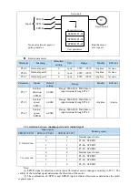
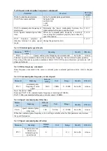
1. No terminal output signal is assigned by default. The parameter range is 0000-0014, which is
allocated to other output terminals through parameter P5-45.
2. When a warning occurs, the servo unit only outputs the warning and will not be forced to set OFF.
5.7.5.5 Alarm output (/ALM)
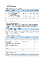
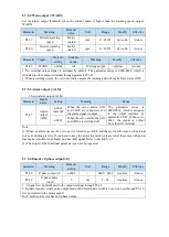
1. Servo alarm output /ALM
Parameter
Signal
name
Setting
Meaning
Range
P5-47
Alarm
output
/ALM
n.0002
(default)
When the servo alarm, SO2
and COM are connected, and
the alarm signal is output.
The
parameter
range
is
0000-0014, which is assigned
to the output interface by
parameter P5-47. When set to
0001, the signal is output
from the SO1 terminal.
n.0012
When the servo alarm, the SO2
and COM are switched off.
Note:
(1) When an alarm occurs, the servo unit is forced to set OFF, and the motor will move with external
forces (including gravity). If you need to keep the motor in position, please select the motor with power
loss brake (also known as brake) and use / BK signal. Refer to Section 5.2.5.
(2) The output of the functional parameters can not be repeated.
5.7.5.6 Encoder Z phase output (/Z)
parameter
Meaning
Default
setting
Unit
Range
Modify
Effective
P5-48
Z phase output /Z
n.0000
-
0000
~
0014
Anytime
At once
P5-19
Z phase pulse
width
2
ms
2
~
20
Anytime
At once
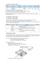
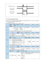
1. /Z signal can be distributed to the output terminal through P5-48.
2. Z phase signal is single pulse output mode, the default pusle width is 2ms, it can set through P5-19,
it is not related to the motor speed.
Note: multi-turn motor has no Z phase output.
Summary of Contents for DS5L1 Series
Page 1: ...DS5L1 series servo driver User manual WUXI XINJE ELECTRIC CO LTD Data No SC5 05 20200929 1 0 ...
Page 2: ......
Page 6: ......
Page 100: ...3 Set the auto tuning interface 4 Click ok to start inertia identification ...
Page 106: ...3 set the auto tuning interface ...
Page 112: ...with higher rigidity 6 Start auto tune 7 Open the servo enable then click ok ...
Page 169: ...Appendix 9 Torque speed characteristic curve ...
Page 170: ......

