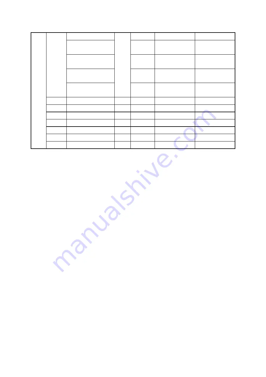
(module 13)
QD11300~QD11399
(module 14)
100
11300~11399
2C24~2C87
QD11400~QD11499
(module 15)
100
11400~11499
2C88~2CEB
QD11500~QD11599
(module 16)
100
11500~11599
2CEC~2D4F
QD20000~QD20099
(BD 1)
100
20000~20099
4E20~4E83
HD
HD0~HD24999
136
25000
0~24999
0~61A7
HTD
HTD0~HTD1999
137
2000
0~1999
0~7CF
HCD
HCD0~HCD1999
138
2000
0~1999
0~7CF
HSCD
HSCD0~HSCD39
139
40
0~39
0~27
HSD
HSD0~HSD1999
140
2000
0~1999
0~7CF
FD
FD0~FD8191
141
8192
0~8191
0~1FFF
SFD
SFD0~SFD5999
142
6000
0~5999
0~176F
Note:
1. The input and output is octal, please calculate the input and output X-NET address as octal.
2. make sure there is no cross-border access for the target object.
1-4. X-NET Communication application
There are two XD3 sereis PLC. They communicate with each other through XD-RS485-BD based
on X-NET protocol.
The purposes:
1. Write PLC A register D0~D9 to PLC B D0~D9
2. Write PLC A coil M0~M9 to PLC B M0~M9
3. Read PLC B register D0~D9 to PLC A D10~D19
4. Read PLC B coil M0~M9 to PLC A M10~M19
Step 1: wiring
Connect terminal A to A, terminal B to B of the XD-RS485-BD.
Step 2: RS485 port setting
1. Connect PLC A with PC through USB cable. Open the XINJEConfig software.


