background image

M

M

I

I

C

C

S

S

P

P

R

R

O

O

G

G

R

R

E

E

S

S

S

S

A

A

4

4

0

0

0

0

-

-

A

A

5

5

0

0

0

0

G

GR

RO

OU

UP

PE

ES

S É

ÉL

LE

EC

CT

TR

RO

OG

ÈN

NE

ES

S - G

GE

EN

NE

ER

RA

AT

TIIN

NG

G S

SE

ET

TS

S

G

GR

RU

UP

PO

OS

S E

EL

LE

EC

CT

TR

RO

OG

GE

EN

NO

OS

S - G

GE

ER

RA

AD

DO

OR

RE

ES

S E

EL

ÉC

CT

TR

RIIC

CO

OS

S

S

ST

TR

RO

OM

ME

ER

RZ

ZE

EU

UG

GE

ER

R - G

GR

RU

UP

PP

PII E

EL

LE

ET

TT

TR

RO

OG

GE

EN

NII - G

GE

EN

NE

ER

RA

AT

TO

OR

RA

AN

NL

ÆG

G

D

DIIE

ES

SE

EL

LG

GE

EN

NE

ER

RA

AT

TO

OR

RA

AG

GG

GR

RE

EG

GA

AT

T - A

AG

GG

GR

RE

EG

GA

AT

TE

ER

R - A

AG

GG

GR

RE

EG

GA

AT

TE

EN

N

D

DIIE

ES

SE

EL

LA

AG

GG

GR

RE

EG

GA

AA

AT

TIIT

T - R

RA

AF

FS

ST

ÖD

DV

VA

AR

R - 

Ã

ÃÅ

ÅÍ

ÍÅ

ÅÐ

ÐÀ

ÀÒ

ÒÎ

ÎÐ

ÐÍ

ÍÛ

ÛÅ

Å ÓÓÑ

ÑÒ

ÒÀ

ÀÍ

ÍÎ

ÎÂ

ÂÊ

ÊÈ

È 

Rédacteur : Sce Doc.

Vérificateur : B.E.E.

Approbateur : Sce Doc

Administrateur : Sce Doc.

L

Le

es

s rre

ec

ch

he

errc

ch

he

es

s p

pe

errm

ma

an

ne

en

ntte

es

s d

de

e n

no

os

s b

bu

urre

ea

au

ux

x d

d’’é

éttu

ud

de

es

s,, a

aiin

ns

sii q

qu

ue

e ll’’a

am

élliio

orra

attiio

on

n c

co

on

nttiin

nu

ue

elllle

e d

de

e n

no

os

s p

prro

od

du

uiitts

s,, e

en

ng

ga

ag

ge

en

ntt n

no

ottrre

e S

So

oc

ciié

étté

é à

à s

se

e rré

és

se

errv

ve

err lle

e d

drro

oiitt d

de

e

tto

ou

utte

es

s m

mo

od

diiffiic

ca

attiio

on

ns

s s

sa

an

ns

s p

prré

éa

av

viis

s..

T

To

ou

us

s d

drro

oiitts

s d

de

e m

mo

od

diiffiic

ca

attiio

on

ns

s d

de

es

s p

prré

és

se

en

ntts

s m

ma

an

nu

ue

ells

s rré

és

se

errv

és

s..

R

Re

ep

prro

od

du

uc

cttiio

on

n e

ett ttrra

ad

du

uc

cttiio

on

n,, m

êm

me

e p

pa

arrttiie

elllle

e,, iin

ntte

errd

diitte

e s

sa

an

ns

s a

au

utto

orriis

sa

attiio

on

n s

sp

éc

ciia

alle

e..

C

Co

on

nc

ce

ep

pttiio

on

n e

ett rré

éa

alliis

sa

attiio

on

n :: S

Se

errv

viic

ce

e d

de

e d

do

oc

cu

um

me

en

ntta

attiio

on

n

à

à p

pa

arrttiirr d

de

es

s d

do

oc

cu

um

me

en

ntts

s s

su

uiiv

va

an

ntts

s ::

B

Ba

as

se

e d

do

oc

cu

um

me

en

ntta

aiirre

e c

co

on

ns

sttrru

uc

ctte

eu

urr g

grro

ou

up

pe

es

s é

élle

ec

cttrro

og

èn

ne

es

s +

+ D

Do

oc

c B

BE

EE

E                                                                       P

Pa

ag

giin

na

attiio

on

n :: 2

25

5 p

pa

ag

ge

es

s ((O

O à

à A

A +

+ 1

1 à

à 2

23

3)) 

C. RESSEGUIER

P. PLAZENET

© Publication : ref G.P.A.O.33502003001

user’s

user’s

instructions

instructions

ShenZhen XinKe power equipment Co .Ltd

Summary of Contents for A400

Page 1: ...pr ro od du ui it ts s e en ng ga ag ge en nt t n no ot tr re e S So oc ci ié ét té é à à s se e r ré és se er rv ve er r l le e d dr ro oi it t d de e t to ou ut te es s m mo od di if fi ic ca at ti io on ns s s sa an ns s p pr ré éa av vi is s T To ou us s d dr ro oi it ts s d de e m mo od di if fi ic ca at ti io on ns s d de es s p pr ré és se en nt ts s m ma an nu ue el ls s r ré és se er rv v...

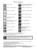
Page 2: ...protected Compulsory stacking point Water based fire extinguishers forbidden A 02 99 Due to on going research in our design offices and the continuous improvement of our products our Company reserves the right to make changes without prior notice All rights to change the contents of the current manuals reserved Reproduction and translation even partial forbidden without special authorisation Desig...

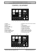
Page 3: ... remote in Version IV V 13 MICS Progress 14 4 position function switch 15 Oil temperature gauge 16 Battery ammeter gauge 17 Shutdown extractor light 18 MDEC synthesis alarm light 19 Lack of water preheating light 20 Retention tank warning light 21 Test lamps push button Progress can be factory configured in several ways Any further changes will have to be submitted to our company prior consent A H...

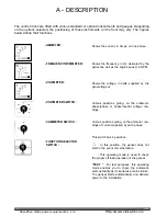
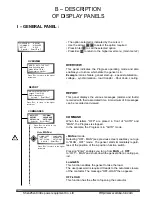
Page 4: ...ing mode is used to check the proper off load operation of the genset TEST For test purposes this operating mode enables you to check the automatic start up facility as it simulates a mains failure The genset starts automatically and delivers power to the installation A DESCRIPTION The control racks are fitted with various standard or optional instruments and gauges Depending on the options select...

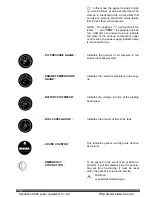
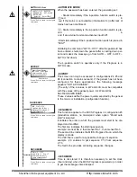
Page 5: ...e in the engine lubricating system Indicates the coolant temperature in the engi ne Indicates the voltage in Volts of the starting battery ies Indicates the amount of fuel in the tank This totals the genset running hours as soon as it starts To be pushed in the event of an accident or problem it will immediately stop the genera ting set from functioning It must be reset when the genset is returned...

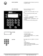
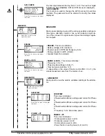
Page 6: ...unction genset genset or genset mains Paralleling function genset genset or gen set mains Load distribution function between gensets The screen allows you to view all alarms and faults the genset operating states various parameters which can be modified with access code The keypad ensures modification of the follo wing delays set up thresholds genset general parameters basics access to the various...

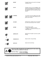
Page 7: ...lt lamp Restarting the genset will not be possible until the fault has been RESET In a window the Left and Right arrows enable access to the various options offered see next page for list of screens Pressing this key enables access to the higher level screen see next page for list of screens Pressing this key enables 1 Access to the value of a parameter 2 Validation of a command or the value of a ...

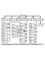
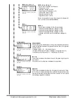
Page 8: ... 0 A 1 B S I W shutdown I Warning IN 1 16 In 1 2 3 4 5 6 7 8 9 0 1 2 3 4 5 6 N O N C Select Enter Esc Γ Battery Volts 23 8 MPU 1513 rpm 50 36 Hz kW Hours 00 001 234 HoursRun 000 150 10 Gen Volts Amps Hz Φ A 221 115 50 07 Φ B 222 117 kW Φ C 220 125 69 9 MAINS or BUS Mains Φ Α Frequency Hz 50 14 Voltage Vrms 223 Distorsion THD 0 1 SYNCscope Gen Φ A v Mains or BUS Φ A Freq Slip Hz 0 07 Phase Shift 11...

Page 9: ...ion function switch Pressing Enter enables you to go from MAN OFF to OFF MAN and shuts down the genset after a cooling per iod Load GEN This function enables the genset to take the load The user password is required It leads to the automatic closure of the contactor The message OFF LOAD then appears OFF LOAD This function has the effect of opening the contactor 02 99 7 MODE AUTO TUE 22 37 Sets Run...

Page 10: ...ction applies to the MICS Progress in configuration 3 production station no mains and when option Parall auto start is selected It enables the order in which the gensets must start to be dis played and modified The first line indicates the starting sequence example Genset No 2 then Genset No 1 then Genset No 3 The second line indicates the MICS Progress No on which the display is made The third li...

Page 11: ...ncy in Hz Energy supplied in kWh stored Genset Hours Run stored MAINS or BUS This screen indicates Frequency in Hz Phase neutral voltage in Volts Total harmonic distortion depending on the value of mains control INS 0 or 1 the values measured come from the mains or bus GENERATOR Main panel to view the electric variables relating to the alterna tor ENGINE Battery Volts 23 8 MPU 1513 rpm 50 36 Hz kW...

Page 12: ...ffective voltages in Volts Press Esc to return to the higher level menu Press Esc to return to the higher level menu Press Esc to return to the higher level menu Press Esc to return to the higher level menu Press Esc to return to the higher level menu SYNCSCOPE This screen gives information on the synchronisation status bet ween the genset between the genset and the bus or the genset and the mains...

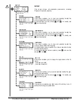
Page 13: ...l through use the arrows and To modify use and the keypad FACTORY This screen is available only after entry of the factory code It defines the factory set parameters SET UP DELAYS SET POINTS OPTIONS IN 1 16 BASICS FACTORY Select Enter Esc Γ DELAIS Set Overspeed 3 0 Gen OverVolts 1 0 Gen OverVolts 1 0 Gen OverVolts 1 0 SETPOINTS User Password 1 Crancking attempts 3 Overspeed RPM 1650 Crankstop RPM ...

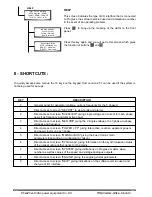
Page 14: ...reen REPORT to view faults and alarms 2 Direct access to screen OVERVIEW giving single voltage and current for each phase as well as frequency and total active power 3 Direct access to screen GEN ΦΦ giving the 3 single voltages the 3 phase to phase voltages and frequency 4 Direct access to screen POWER PF giving total active reactive apparent powers and power factor on each phase 5 Direct access t...

Page 15: ...stability depending on the voltage configuration on V4 Standby On Delay after mains failure before the genset starts in automatic mode with control INS 1 Stanby Off Delay after mains return before load is removed from genset in automatic mode with control INS 1 Eng Preglow Delay for preheating of air intake glow plug s before start up Engine crank Time for starter to trigger period of one attempt ...

Page 16: ...n 16 not activated time before the export quota in kVAr decreases R 1 Off On When option R 1 Trip kW Load is at 1 it is the time before relay 1 is excited R 1 On Off When option R 1 Trip kW Load is at 1 it is the time before relay 1 is de excited Parll Start When option Parall Auto Start is at 1 it is the delay assigned to the genset before its start up on a load increase Parll Stop When option Pa...

Page 17: ...age for the rated speed Gov Volt Bias Phase shift authorised for the paralleling of V1 and V4 V1 genset phase 1 voltage V4 mains or bus phase 1 voltage SYNC Window V Voltage difference authorised for the paralleling of V1 and V4 V1 genset phase 1 voltage V4 mains or bus phase 1 voltage SYgain V 180 Value of off load synchronisation gain SYg V 180 Value of on load synchronisation gain SYstbl V Hz V...

Page 18: ...a dynamic check of the power kVAr kW Xre R 1 On Not used kW Xre R 1 Off Not used kW Xre Start Value expressed as a percentage of the genset power that allows the next genset to start up in a sequence only used in configuration 3 with automatic program Parall Auto Start See Standard applications kW Xre Stop Value expressed as a percentage of the genset power that allows the next genset to shut down...

Page 19: ...t down alarm GENCON low DC S W On sensing a low level of supply voltage 0 leads to engine shut down fault 1 does not lead to engine shut down alarm Generic configure Choosing this option allows to make specific applications which are not defined in the docu ment Standard Applications No 33502002401 Parallelin System The option configured at 1 enables the use of all synchronisation functions for pa...

Page 20: ...les the use of alarm inputs for unused optional faults In 08 Aux Shutdn Enables the use of alarm inputs for unused optional faults In 09 Aux Shutdn Enables the use of alarm inputs for unused optional faults In 12 Aux Shutdn Enables the use of alarm inputs for unused optional faults D BASICS GENERAL PARAMETERS Controller ID No Progress ID between 1 and 8 A unique value must be allocated to each Pro...

Page 21: ...GINE SHUT DOWN FAIL This message indicates that the fuel solenoid is not being supplied ENGINE SLOWCRANK This message indicates that the genset speed is below 60 rpm 2 seconds after the starter has been activated EXTERNAL OVERLOAD When input In 14 is activated this indicates an overload or a short circuit leading to the opening of the circuit breaker FREQENCYNOT BUILT This message indicates that t...

Page 22: ...B1 When input In 11 is activated this indicates a low fuel level which does not lead to engine shut down alarm LOW OIL PRESS SHUTDN OB1 When input In 5 is activated this indicates a low oil pressure which leads to immediate engine shut down fault LOW OIL PRESS WARNIN OB1 When input In 6 is activated this indicates a low oil pressure which does not lead to engine shut down alarm LOW WATER LEVEL Whe...

Page 23: ...mmediate engine shut down SYNCHRONIZER TIME OUT This message indicates that the synchronisation delay assigned to the genset has been exceeded UNEXPECTED BUS VOLTS This message indicates that voltage is available on the bus while logically it should not be VOLTAGE NOT BUILT This message indicates that the alternator voltage has not been stabilised even after a preset period SET UP OPTION Generic P...

Page 24: ...iod An adjustable delay in menu SET UP DELAYS sets the time during which the genset will run manually Automatic operation To start in automatic mode the 4 position function switch must be moved to AUTO The genset is on stand by and Progress awaits a command to start This command comes from information V4 mains or bus mains failure or bus available or external information In both cases the genset s...

Page 25: ...t the operating mode of the selected configuration consult the document no 335 02 002 401 This document shows in detail the operation of the various standard configurations applicable to the MICS Progress 02 99 23 Http www xinke hk com ShenZhen XinKe power equipment Co Ltd ...

Reviews: