background image

DarkStar

 ®

Lighting the path to network independence


User Guide v3.1 

Summary of Contents for DarkStar DRA

Page 1: ...DarkStar Lightingthepathtonetworkindependence UserGuidev3 1...

Page 2: ...U S Government is subject to the restrictions described in FAR 48 CFR 52 227 14 or DFARS 48 CFR 252 227 7014 as applicable Technical Data acquired by or for the U S Government if any is provided with...

Page 3: ...cryptsoft com The SSLeay library is free for commercial and non commercial use as long as the following conditions are adhered to The following conditions apply to all code found in this distribution...

Page 4: ...this software may not be called OpenSSL nor may OpenSSL appear in their names without prior written permission of the OpenSSL Project 6 Redistributions of any form whatsoever must retain the followin...

Page 5: ...t of conditions and the following disclaimer in the documentation and or other materials provided with the distribution THIS SOFTWARE IS PROVIDED BY THE AUTHOR AND CONTRIBUTORS AS IS AND ANY EXPRESS O...

Page 6: ...Enterprises Inc makes no representations about the suitability of this software for any purpose It is provided as is without express or implied warranty University of Michigan Merit Network Copyright...

Page 7: ...ranted to make and use derivative works provided that such works are identified as derived from the RSA Data Security Inc MD5 Message Digest Algorithm in all material mentioning or referencing the der...

Page 8: ...n Systems DBA L DRA 3 DBA L Systems 4 DRA Systems 4 Band Combiner Devices DBC 5 Key Benefits 6 Network System 6 Hardware 6 Software 6 2 Hardware 9 Power 9 Power Requirements 9 AC Power 9 DC Power 9 Da...

Page 9: ...4 Redundancy APP 24 Administrative Access 27 Console Serial Interface 27 Telnet Access 28 Console Jack Pinout Configuration 28 SSH Access 29 SSH Key Replacement 29 Loopbacks 30 Management Network Serv...

Page 10: ...54 Create a saved configuration for backup 54 Getting operational again quickly 54 Automatic recovery from a warm restart 55 Automatic recovery from a cold boot or power recycle 55 Manual crash recove...

Page 11: ...x www xkl com CHAPTERS...

Page 12: ...mand line interface with router like operation that will be familiar to any enterprise network administrator 1 1 1 Network A DarkStar network consists of at least two Darkstar optical networking syste...

Page 13: ...calculated using site installation metrics to determine the optical power required in a system It is often assumed that the more optical power a system offers the better it will perform In the world...

Page 14: ...plification systems share much of the same hardware and software as other DarkStar products requiring only one set of general operating instructions and commands to manage DarkStar products efficientl...

Page 15: ...is amplified WARNING EDFAscanproducehigh energysignalsthatposearisktohumaneyesight Furthermore an improperly configured EDFA can damage optical receivers both within the EDFA equipped DarkStar systems...

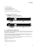
Page 16: ...sive device FIGURE 1 3 DarkStar Band Combiner Devices 9 5 3 4 65 63 9 7 9 62 36 367 6 7 9 9 4 5 05 05 05 6 05 6 05 9 4 5 Console Port Alarm LED s Line Port LED s Ethernet Management Ports East West Li...

Page 17: ...in a DarkStar network may provide total transmission distances of up to 2000km 1 4 2 Hardware DarkStar hardware features include Low Power Consumption Every system in the DarkStar family is rated at 6...

Page 18: ...can be hosted on a remote server to automate configuration of DarkStar systems Employ this feature to recover system settings upon reboot or to automatically provision multiple systems Management Netw...

Page 19: ...same for all systems Power supply modules use either AC or DC power 2 1 1 Power Requirements For maximum availability DarkStar systems should be connected to two power circuits The circuits may be AC...

Page 20: ...be used to complete wiring The table details wiring specifications for both 48V and 48V rails WARNING When connecting wires to the Input Terminal the ground connector GND must be connected first and d...

Page 21: ...ith care and re secure the bail after re inserting the power cord FIGURE 2 2 Replacing Power Supply Modules IF DC POWER latch 1 2 3 4 Click 5 6 Unplug the power cord from the power supply module Disen...

Page 22: ...when securing screws Fans are spinning 6 Fan Controller 0 Fan Controller 2 Unit 0 Unit 1 2 Caution fans are spinning 2 1 Locate the fan module in question The show environment fan command describes th...

Page 23: ...aser Module The OSC laser module is located beneath the top access panel of the DarkStar system chassis 2 3 2 Optical Provisioning Optical interfaces are software configurable You use the DXMOS interf...

Page 24: ...y DRA system to properly clean the E2000 connector prior to instal lation FIGURE 2 4 Replace Laser Module Don tbendseverely 1 2 3 Slide the system forward on its rails far enough to access the panel D...

Page 25: ...e Tx Rx _ show interfaces Important 7 8 9 Insert the replacement laser module into the cage It will click when properly seated It may be helpful to compare its alignment with adjacent lasers to verify...

Page 26: ...lose the hatch by sliding the access panel back to its original position Secure it by tightening the screws with a Phillips head screwdriver Only a quarter turn is required to fasten each screw 11 Sli...

Page 27: ...Conventions for DXMOS Syntax Format Meaning localhost All text appearing on the command line is represented by Courier Standard font show interfaces User entries are represented by Courier Standard bo...

Page 28: ...line CTRL N Scroll forward through the command history CTRL P Scroll backward through the command history CTRL R Redraw the current command input useful for restoring what was typed if the system writ...

Page 29: ...IPv6 working IPv6 addresses are assigned using IPv6 Stateless Address Autoconfiguration see RFC 2462 This requires that there be at least one IPv6 router accessible on the local link The router should...

Page 30: ...ic To reset the software only Press and immediately release the front reset button Software reset maintains power and the state of customer traffic if the running configuration is identical to the sta...

Page 31: ...s that trigger boot and recovery scenarios and their effects on the DarkStar system Please note that in the above table Push and release means pushing the button and immediately releasing it Push and...

Page 32: ...gy requires otherwise 3 Type configure to enter configuration mode 4 Type connect client x wave y encapsulation z x is the client interface to be connected y is the wave channel to be connected z is t...

Page 33: ...onnect client interface 0 to wave channel 0 with a SONET OC192 encapsulation localhost enable localhost configure TABLE 3 4 Available Protocols Data Rates and corresponding Encapsulation Protocol Gb s...

Page 34: ...ilarly localhost enable localhost configure localhost CONF interface ethernet 0 localhost CONF INT ETH 0 ip address 192 168 0 1 24 localhost CONF INT ETH 0 end localhost write memory Are you sure yes...

Page 35: ...Software www xkl com working interface must be accomplished manually This configuration may be desired because switching between currently selected resources incurs a brief disruption to the link mea...

Page 36: ...mance In such a case it may be useful to set a holdoff value which specifies the time duration before an APP group reverts from the working to the protection interface Holdoff time is specified in mil...

Page 37: ...it is also possible to administer the system from a remote virtual VTY terminal using telnet or SSH Secure Shell 3 2 5 1 Console Serial Interface The console serial port is a minimal RS 232 Data Term...

Page 38: ...e login over VTY The transport input telnet command configures VTY to accept login attempts via the telnet protocol The following example illustrates how to configure remote telnet access to all confi...

Page 39: ...ient will ask the console operator to confirm the SSH access request subsequent SSH console access requests authenticate silently 3 2 5 4 SSH Key Replacement A DarkStar system ships with SSH keys alre...

Page 40: ...xists is used as the source address for outbound IP messages instead of the IP address of the physical interface However if the Loopback Address is unconfigured the IP address of the physical interfac...

Page 41: ...TC 7 Mon Mar 30 2009 If you run an SNTP server on a network reachable by the DarkStar system the command sntp server hostname will enable the clock to be set from the SNTP server 3 2 9 Remote File Con...

Page 42: ...cast In this scenario you may use any active interface s client identifier or source MAC address in the corresponding DHCP server configuration file Be aware however that if the Ethernet interface or...

Page 43: ...DarkStar system s settings An enabled mode password will prompt for a password when the enable command is used The following example illustrates how to assign a password for enabled mode Assigning a p...

Page 44: ...re localhost CONF line console localhost CONF LINE CTY no password localhost CONF LINE CTY end localhost write memory Are you sure yes no yes The following example illustrates how to create CTY user a...

Page 45: ...based on the order that the entries occur in the router The router searches for matches and denies traffic if no match is found There is an implied denial for traffic that is not permitted A single en...

Page 46: ...authenti cation authorization and accounting services The use of AAA services also allows more precision and control when using local login methods The TACACS protocol uses TCP and is not compatible...

Page 47: ...DFAs When a DXM or DSM is looped back on itself an attenuator is required to reduce output power This will prevent the receivers from getting damaged OPTIONAL Tx Tx Tx Tx Tx MUX FIXED ATTENUATOR EDFA...

Page 48: ...NO SHUTDOWN DO SHOW INTERFACE SUMMARY CONTROL OUTPUT POWER 5 0 DXM 5R CONTROL OUTPUT POWER 2 0 DXM 10 WAVE LASER RECEIVE POWER BETWEEN 14 AND 18 SHUTDOWN END WRITE MEMORY NO YES NO YES EDFA WEST 1 BO...

Page 49: ...ONF EDFA WEST 0 Amplifier edfa west 0 amplification up localhost CONF EDFA WEST 0 exit localhost CONF do show interfaces summary Switch Interfaces Summary Admin Line Rate kHz RxPow Ch Alarms Last Line...

Page 50: ...2 Up Down 10GE 18 0 dBm 52 None 0 01 18 40 Wave West 1 Up Down 10GE 17 2 dBm 51 None 0 01 18 40 Wave West 0 Up Down 10GE 18 1 dBm 50 None 0 01 18 40 Admin Line Type IP Address Loopback 0 Up Up Loopbac...

Page 51: ...A input power using the show edfa command Use the EDFA control output gain command to restore the default 22dB EDFA gain if necessary Use a show raman command to find the current Raman gain setting th...

Page 52: ...9 19 Client 7 Up Down 10GE 40 0 dBm N A Alarm 1 18 40 49 Client 8 Up Down 10GE 19 1 dBm N A OK 1 18 40 49 Client 9 Up Down 10GE 18 8 dBm N A OK 1 18 40 49 Wave 0 Up Alarm 10GE 13 3 dBm 30 OK 0 22 02 2...

Page 53: ...ed Wavelength 1310nm I2C Address 0 5 80 General Status Administrative State Up Transmitter Disabled Receiver LOS Error Forwarding Laser Shutdown by Virtualight Total Down Error Time 153828s Time Since...

Page 54: ...High Alarm 1 9dBm High Warning 0 9dBm Low Warning 7 0dBm Low Alarm 8 0dBm Tx Laser Bias Current 0 0mA High Alarm 85 0mA High Warning 80 0mA Low Warning 12 0mA Low Alarm 7 0mA CDR Temperature 39C CDR...

Page 55: ...probably already damaged and will be shut off immediately to prevent possible damage to other DarkStar components In addition to the temperature sensors provided by individual components of the DarkSt...

Page 56: ...ntents of the log buffer localhost show log 0 01 45 15 Authentication Success 10 15 1 98 0 01 46 17 Authentication Failure 10 15 1 98 0 01 46 22 Authentication Success 10 15 1 98 3 3 4 SNMP DarkStar s...

Page 57: ...ic Trap Types Trap Trap Type Event 1 xklFanFail A fan module has failed or has some other problems 2 xklPowerFail A power supply module has failed or has some other problems 3 xklFanUp A fan module ha...

Page 58: ...Error detection at optical frequencies is at the physical layer of the network stack DarkStar systems rely on signal integrity indicators from the laser interfaces and Clock and Data Recovery CDR circ...

Page 59: ...eceivers The signal integrity error is detected consistently further downstream Some modules may report incorrect statuses when error forwarding occurs Therefore it may be possible for different modul...

Page 60: ...logging files Issue a bert transmit on the transmitting interface to initiate PRBS generation followed by a bert receive command that initiates checking of the PRBS stream begins counting errors and...

Page 61: ...t accumulates a count of samples If you configure the BERT as verbose then a new log entry is created for each sample even if Total Errors remains continuously at zero Test results are visible at the...

Page 62: ...to verify a BER of 10 12 at 85 99 levels of confidence for a SONET and a 10GE link FIGURE 3 5 BERT test times required for BER 10 12 From the table on a SONET link at 9 953Gbps BERT test time needs t...

Page 63: ...he configuration file runs automatically at boot time It includes not only system and network settings but also configures management services such as SNMP and event logging that need to be in place f...

Page 64: ...l and xkl generic otherwise by default SNMP will send you all possible SNMP network traps Enable the AAA feature using the aaa new model command so that TACACS logs an auditable account of configura t...

Page 65: ...light is reaching them No system dump file is available 4 1 2 6 Manual crash recovery only if automatic recovery fails You will need to intervene manually in the boot process if the system can t resta...

Page 66: ...older passwords Review and verify operator passwords in use No serial connection no activity at console Faulty cable connection Incorrect or faulty cable Check connection and reseat if necessary Repla...

Page 67: ...connected Dirty fiber Failed laser or XFP SFP module s Connect with clean fiber Replace failed component DarkStar modules are hot swappable LOS Loss of Signal or LOL Loss of Lock on client or wave int...

Page 68: ...ow led command shows these LED patterns at a remote operator console TABLE 4 3 LED Legend LED Status Meaning Steady off Steady on Flashing TABLE 4 4 Front Panel LED Patterns PWR green WRN amber ALM re...

Page 69: ...trongly encourages you to maintain current copies of your configuration using the write memory and write network commands whenever configuration changes are made The following example shows system rec...

Page 70: ...ch board 00085 01 Initializing DarkStar DSM10 5R Initializing environmental loader Running startup gateware Done Power NOT Cycled Mounting file system User Enabling TX laser on interface OSC 0 W User...

Page 71: ...ion about DarkStar system functions and network operations In a production network using debug can generate a high volume of trace information at the console and may degrade system performance so XKL...

Page 72: ...50103 50003 10...

Reviews: