
XLT Ovens
PO Box 9090
Wichita, Kansas 67277
TEL: 888-443-2751 FAX: 316-943-2769 WEB SITE: www.xltovens.com
XLT Oven & AVI Hood
Installation & Operation Manual
XD-9010B-GA
Rev 03 04/07/2011
2000887
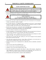
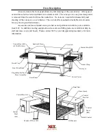
This appliance is for professional use by qualified personnel. This appliance must be installed
by qualified persons in accordance with the regulations in force. This appliance must be installed with
sufficient ventilation to prevent the occurrence of unacceptable concentrations of substances harmful
to health in the room in which it is installed. This appliance needs an unobstructed flow of fresh air for
satisfactory combustion and must be installed in a suitably ventilated room in accordance with current
regulations. This appliance should be serviced by qualified personnel at least every 12 months or
sooner if heavy use is expected.
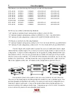
For use with the following AVI Hood Versions:
Standard (S)
A
World (W)
A
For use with the following XLT GAS Oven Versions:
Australian (AE) B
Standard (S)
B
World (W)
B
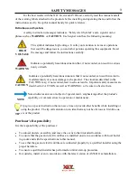
CAUTION
An electronic copy of this manual & warranty policy is available at: www.xltovens.com
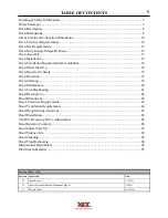
Summary of Contents for 1832-AE-B
Page 43: ...43 This page intentionally left blank ...
Page 88: ...This page intentionally left blank ...
Page 95: ...95 Oven Schematic 1832 2440 3240 3255 3855 Square Burner Standard ...
Page 96: ...96 Oven Schematic 1832 2440 3240 3255 3855 Square Burner World ...
Page 97: ...97 Oven Schematic 1832 2440 3240 3255 3855 Round Burner Australia ...
Page 98: ...98 Oven Schematic 3270 3870 Square Burner Standard RH Control Box ...
Page 99: ...99 3270 3870 Square Burner Standard LH Control Box Oven Schematic ...
Page 100: ...100 Oven Schematic 3270 3870 Square Burner World RH Control Box ...
Page 101: ...101 Oven Schematic 3270 3870 Square Burner World LH Control Box ...
Page 102: ...102 3270 3870 Round Burner Australia LH Control Box Oven Schematic ...
Page 103: ...103 Oven Schematic 3270 3870 Round Burner Australia RH Control Box ...
Page 104: ...104 Hood Schematic Standard ...
Page 105: ...105 Hood Schematic World ...


