


28
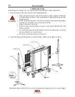
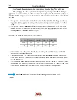
Ventilation Requirements & Guidelines
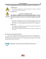
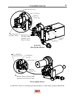
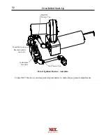
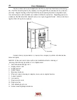
Oven Initial Start-Up
All XLT ovens are test-fired at the factory. Operation is verified, and adjustments are
made to ensure proper function. However, field conditions are sometimes different than factory
conditions, such as voltage and fuel pressure. These variables make it necessary to have an author-
ized service technician verify operation and make field adjustments if needed. The following
items must be checked and verified to meet the specifications and requirements stated in this man-
ual prior to the oven being commissioned:
Fuel line pipe size
Fuel pressure (static)
Fuel pressure (dynamic)
Proper electrical connections
Proper ventilation
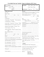
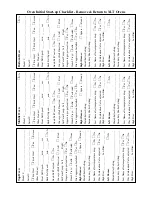
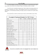
The following Initial Start-Up Checklist must be completed (both sides) at time of installation,
signed by the Customer and returned to XLT Ovens to initiate Warranty Policy.
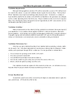
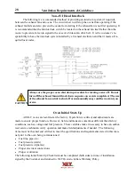
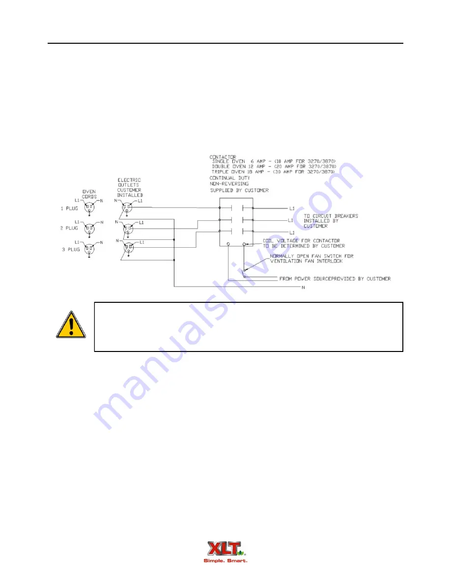
Non-AVI Hood Interlock
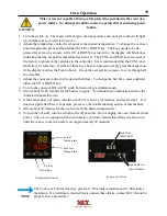
Always use the proper oven shut down procedure for turning ovens off. Do not
turn off the exhaust fan until cool down sequence on oven is completed. The use
of the exhaust fan control to shut off ovens manually may void the warranty on
ovens.
The following is a recommended method of providing an interlock system (if required),
between the exhaust fan and ovens. The circuit shown will stop the ovens from operating if the
exhaust fan fails and also prevent the ovens from starting if the exhaust fan is not first operating. It
is recommended that the fan interlock switch be located on the exhaust fan itself rather than the
motor to prevent a false run signal in the case of a broken fan drive belt. It is the customer’s re-
sponsibility to have the interlock system installed by a licensed electrician and that it meets all re-
quired local codes.
CAUTION
Summary of Contents for 1832-AE-B
Page 43: ...43 This page intentionally left blank ...
Page 88: ...This page intentionally left blank ...
Page 95: ...95 Oven Schematic 1832 2440 3240 3255 3855 Square Burner Standard ...
Page 96: ...96 Oven Schematic 1832 2440 3240 3255 3855 Square Burner World ...
Page 97: ...97 Oven Schematic 1832 2440 3240 3255 3855 Round Burner Australia ...
Page 98: ...98 Oven Schematic 3270 3870 Square Burner Standard RH Control Box ...
Page 99: ...99 3270 3870 Square Burner Standard LH Control Box Oven Schematic ...
Page 100: ...100 Oven Schematic 3270 3870 Square Burner World RH Control Box ...
Page 101: ...101 Oven Schematic 3270 3870 Square Burner World LH Control Box ...
Page 102: ...102 3270 3870 Round Burner Australia LH Control Box Oven Schematic ...
Page 103: ...103 Oven Schematic 3270 3870 Round Burner Australia RH Control Box ...
Page 104: ...104 Hood Schematic Standard ...
Page 105: ...105 Hood Schematic World ...


