


73
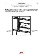
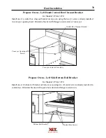
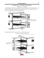
Hood Installation
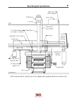
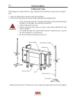
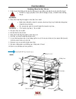
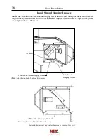
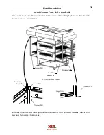
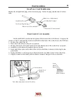
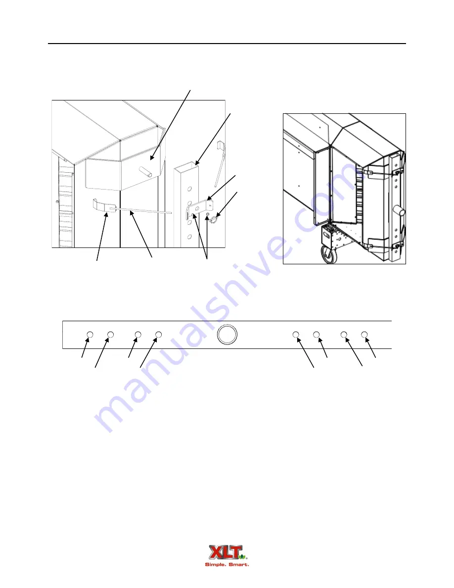
Lifting Gear Setup
Threaded Rod
End Beam
Saddle
Lifting Hook
Bracket
Nuts
Locking Pin
1. Insert end of each threaded rod into the small holes located on bracket so that ends are to the inside of bracket.
2. Thread nuts about 1/2” (12.7mm) onto threaded rod ends.
3. Slide saddle pin through appropriate hole located on End Beam, see placement diagram above.
4. Slide bracket and lifting hook assembly onto saddle pin with bracket resting flat on end beam.
5. Insert locking pin in hole located near end of saddle pin.
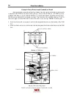
6. Place lifting gear assembly against end of hood with saddle pads against vertical surface.
7. Insert each lifting hook into notch located at corner of fascia end.
8. Tighten nuts on threaded rods until End Beam can not be moved.
Left end shown, right end similar
End Beam
Saddle placement
18xx
24xx
38xx
32xx
18xx
24xx
38xx
32xx
Summary of Contents for 1832-AE-B
Page 43: ...43 This page intentionally left blank ...
Page 88: ...This page intentionally left blank ...
Page 95: ...95 Oven Schematic 1832 2440 3240 3255 3855 Square Burner Standard ...
Page 96: ...96 Oven Schematic 1832 2440 3240 3255 3855 Square Burner World ...
Page 97: ...97 Oven Schematic 1832 2440 3240 3255 3855 Round Burner Australia ...
Page 98: ...98 Oven Schematic 3270 3870 Square Burner Standard RH Control Box ...
Page 99: ...99 3270 3870 Square Burner Standard LH Control Box Oven Schematic ...
Page 100: ...100 Oven Schematic 3270 3870 Square Burner World RH Control Box ...
Page 101: ...101 Oven Schematic 3270 3870 Square Burner World LH Control Box ...
Page 102: ...102 3270 3870 Round Burner Australia LH Control Box Oven Schematic ...
Page 103: ...103 Oven Schematic 3270 3870 Round Burner Australia RH Control Box ...
Page 104: ...104 Hood Schematic Standard ...
Page 105: ...105 Hood Schematic World ...


