


74
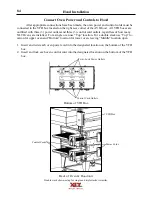
Hood Installation
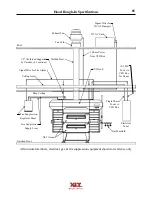
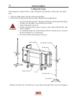
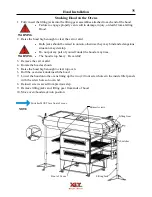
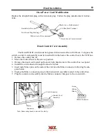
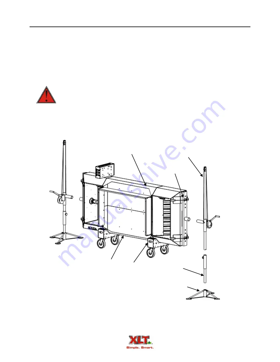
Lifting Jack Setup
Each lifting jack consists of three (3) parts; the pole/winch assembly, extension tube, and tripod
base.
Check for smooth operation. The cable should not be pinched and should pass
smoothly over the pulley on top of the pole assembly.
Inspect cable prior to each use.
If cable is frayed or shows signs of excessive wear and tear, DO NO USE until
cable is replaced.
At a minimum replace the cable annually with wire rope that meets or exceeds
the jack manufacturer’s specifications.
Do not exceed the stated capacity of the jack.
WARNING
1. Place the smaller end of extension tube into tripod base.
2. Place bottom of the pole into the top of the extension tube and tighten knob.
Pole/Winch Assembly
Extension Tube
Tripod Base
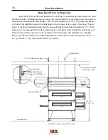
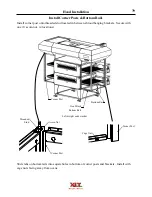
Back of Hood
Bottom of Hood
Cart
Lifting Gear
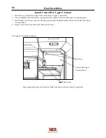
Illustrations shown with AVI hood on cart, same instructions apply when hood is crate shipped.
Summary of Contents for 1832-AE-B
Page 43: ...43 This page intentionally left blank ...
Page 88: ...This page intentionally left blank ...
Page 95: ...95 Oven Schematic 1832 2440 3240 3255 3855 Square Burner Standard ...
Page 96: ...96 Oven Schematic 1832 2440 3240 3255 3855 Square Burner World ...
Page 97: ...97 Oven Schematic 1832 2440 3240 3255 3855 Round Burner Australia ...
Page 98: ...98 Oven Schematic 3270 3870 Square Burner Standard RH Control Box ...
Page 99: ...99 3270 3870 Square Burner Standard LH Control Box Oven Schematic ...
Page 100: ...100 Oven Schematic 3270 3870 Square Burner World RH Control Box ...
Page 101: ...101 Oven Schematic 3270 3870 Square Burner World LH Control Box ...
Page 102: ...102 3270 3870 Round Burner Australia LH Control Box Oven Schematic ...
Page 103: ...103 Oven Schematic 3270 3870 Round Burner Australia RH Control Box ...
Page 104: ...104 Hood Schematic Standard ...
Page 105: ...105 Hood Schematic World ...


