


80
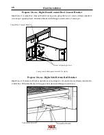
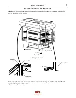
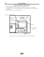
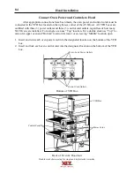
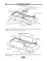
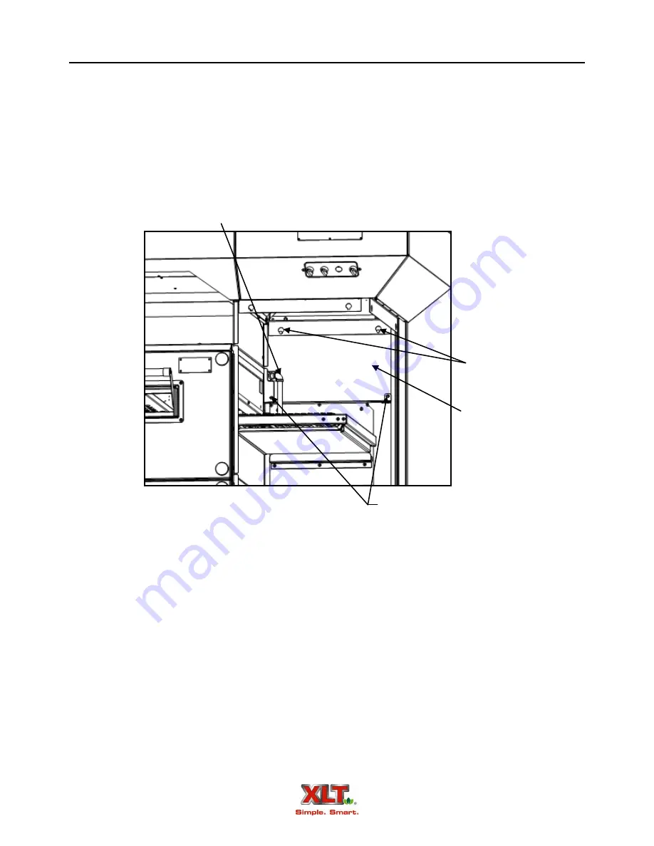
Install Control Box Upper Closeout
Hood Installation
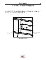
Thumb screws
Keyholes
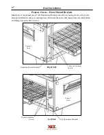
Some components removed for clarity. Right side shown, left side similar if applicable.
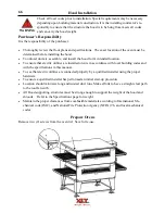
Fire Suppression Piping (optional)
1. Install one (1) Control Box Upper Closeout Panel above upper Control Box.
2. Line up shoulder bolts located near top of panel with keyholes in bracket, allow panel to drop into place.
3. Install thumb screws from conveyor side through previously installed bracket, thread into Control Box Upper
Closeout Panel.
4. Repeat for left side if ovens have left hand control boxes.
Control Box Upper
Closeout Panel
Summary of Contents for 1832-AE-B
Page 43: ...43 This page intentionally left blank ...
Page 88: ...This page intentionally left blank ...
Page 95: ...95 Oven Schematic 1832 2440 3240 3255 3855 Square Burner Standard ...
Page 96: ...96 Oven Schematic 1832 2440 3240 3255 3855 Square Burner World ...
Page 97: ...97 Oven Schematic 1832 2440 3240 3255 3855 Round Burner Australia ...
Page 98: ...98 Oven Schematic 3270 3870 Square Burner Standard RH Control Box ...
Page 99: ...99 3270 3870 Square Burner Standard LH Control Box Oven Schematic ...
Page 100: ...100 Oven Schematic 3270 3870 Square Burner World RH Control Box ...
Page 101: ...101 Oven Schematic 3270 3870 Square Burner World LH Control Box ...
Page 102: ...102 3270 3870 Round Burner Australia LH Control Box Oven Schematic ...
Page 103: ...103 Oven Schematic 3270 3870 Round Burner Australia RH Control Box ...
Page 104: ...104 Hood Schematic Standard ...
Page 105: ...105 Hood Schematic World ...


