


84
Hood Installation
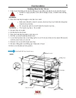
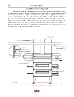
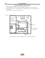
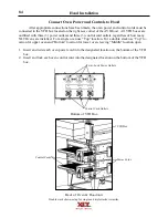
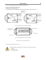
Connect Oven Power and Controls to Hood
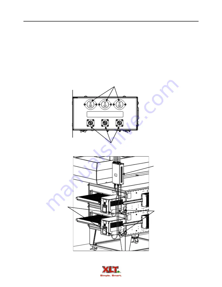
After appropriate connections have been made, the oven power and control cords must be
connected to the VFD box located on the right
back
corner of the AVI Hood. All VFD boxes are
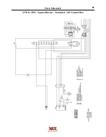
outfitted with three (3) power outlets and three (3) control cord outlets, regardless of how many
XLT Ovens are installed. For a single oven use “Top” location. For a double stack use “Top” lo-
cation for upper oven and “Bottom” location for lower oven, leaving “Middle” location open
.
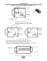
1. Insert and twist each oven power cord into the designated location on the bottom of the VFD
box.
2. Insert and lock each oven control cord into the designated location on the bottom of the VFD
box.
TOP
OVEN
MIDDLE
OVEN
BOTTOM
OVEN
Twist-Lock Power Outlets
Control Cord Outlets
Bottom of VFD Box
Double stack shown, setup for single and triple stacks is similar.
VFD Box
Control Cords
Power Cords
Back of Oven & Hood unit
Summary of Contents for 1832-AE-B
Page 43: ...43 This page intentionally left blank ...
Page 88: ...This page intentionally left blank ...
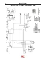
Page 95: ...95 Oven Schematic 1832 2440 3240 3255 3855 Square Burner Standard ...
Page 96: ...96 Oven Schematic 1832 2440 3240 3255 3855 Square Burner World ...
Page 97: ...97 Oven Schematic 1832 2440 3240 3255 3855 Round Burner Australia ...
Page 98: ...98 Oven Schematic 3270 3870 Square Burner Standard RH Control Box ...
Page 99: ...99 3270 3870 Square Burner Standard LH Control Box Oven Schematic ...
Page 100: ...100 Oven Schematic 3270 3870 Square Burner World RH Control Box ...
Page 101: ...101 Oven Schematic 3270 3870 Square Burner World LH Control Box ...
Page 102: ...102 3270 3870 Round Burner Australia LH Control Box Oven Schematic ...
Page 103: ...103 Oven Schematic 3270 3870 Round Burner Australia RH Control Box ...
Page 104: ...104 Hood Schematic Standard ...
Page 105: ...105 Hood Schematic World ...


