background image

Sin, 

le.  Sn,art. 

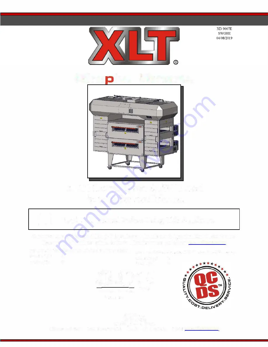
XLT Electric Oven & AVI Hood 

Parts & Service Manual 

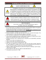
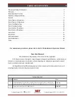
Read This Manual Before Using This Appliance. 

Current versions of this manual, Rough-In Specifications, Installation & Operation Manual, Architectural 

Drawings, & a list oflnternational Authorized Distributors are available at: 

www.x

l

tovens.com 

For use with the followi

ng 

XL T Electric Oven Versions• 

For use with the following A VI Electric Hood Versions• 

Standard (S) 

World (W) 

Standard (S) 

World(W) 

,(fil) .. �C E 

-l1,an;.O 

7'JOt

P•-' 

lntertek  lntertek  0359 

2000887 

XLI Ovens 

PO Box9090 

Wichita, Kansas 67277 

US• 888-443-2751  FAX 316-943-2769  INTL  316-943-2751  WEB 

www

.

x

l

t

ovens

.

com 

Summary of Contents for AVI

Page 1: ... Drawings a list oflnternational Authorized Distributors are available at www xltovens com For use withthe following XLT Electric OvenVersions Foruse withthe following AVI Electric Hood Versions Standard S G World W G Standard S E World W E fil C E l1 an O 7 JOt P lntertek lntertek 0359 2000887 XLI Ovens PO Box9090 Wichita Kansas 67277 US 888 443 2751 FAX 316 943 2769 INTL 316 943 2751 WEB www xlt...

Page 2: ...en in the installed position Keep the area free and clear of combustible material DO NOT SPRAY AEROSOLS IN THE VICINITY OF THIS APPLIANCE WHILE IT IS IN OPERATION Ovens are certified for installation on combustible floors Electrical schematics are located inside the control box of the oven and in this manual Dis connect input power to the unit before performing any maintenance This unit requires a...

Page 3: ...follow the instructions carefully VOLTAGE ISO 7000 0434 Indicates a potentially hazardous situation that ifnot avoided can result in minor to moderate injury or serious damage to the product The situation described in the CAUTION may ifnot avoided lead to serious results Important WARNING safety measures are described in CAUTION as well as WARNING so be sure to observe them ISO 7000 0434 Indicates...

Page 4: ... operated in accordance with the l O Manual furnished with the unit This warranty shall not excuse the owner from properly maintaining the equipment in accordance with the l O Manual furnished with the unit A copy of the Initial Start Up Checklist must be filled out and returned to XLT when the unit is initially installed and or when the unit is removed and installed in another location The gas el...

Page 5: ...nit This warranty shall not excuse the owner from properly maintaining the equipment in accordance with the l O Manual furnished with the unit A copy of the Initial Start Up Checklist must be filled out and returned to Distributor Service Provider when the unit is initially installed and or when the unit is removed and installed in another location The gas electric and HVAC utilities must be conne...

Page 6: ...1 10 24 Tap l 1 9 16 1 8 32 Tap 3 8 Drive Allen 5 8 1 1 8 1 11 16 1 Miscellaneous 3 16 1 3 4 1 Dwyer Manometer 7 32 1 Dwyer A 110 Fluid 1 4 1 Wrenches QTY Volt Amp Meter 5 16 1 10 Crescent 1 Heat Probe 3 8 1 14 Pipe 2 Molex Extractor MolexCrimper T Handle Allen QTY I ScrewDrivers QTY Straight Pick 6 3 32 1 2 Phillips 1 90 Degree Pick 6 7 64 1 1 Phillips 1 7 Zip Ties 1 8 1 1 4 Flat Blade 1 Flashlig...

Page 7: ...tion Operation Manual Stands assembled and set in place X Ovens moved and stacked with proper lifting equipment X Assemble shrouds brackets to XLT Oven Hood X Connecting fuel to XLT products Install piping and drip legs X Weld ducting to XLT Hood X Check for leaks X Install flexible gas hoses X Collllect electrical supply X Connection may require Permit and Code Inspections X Relocate Make Up Air ...

Page 8: ... dimensions weights electrical requirements maintenance schedules and certifications XLT Ovens wants you to be totally satisfied with every aspect ofowning using your oven hood Your feedback both positive negative is very important to us as it helps us un derstand how to improve our products our company Our goal is to provide you with equipment that we can be proud to build you can be proud to own...

Page 9: ...erves the right to make changes in design specifications and or make ad ditions to or improvements to its product without imposing any obligations upon itselfto install them in products previously manufactured All Right Hand Left Hand designations in this manual are from the point ofview as if standing directly in front ofthe glass sandwich door Revision History Table Revision Comments Date D Adde...

Page 10: ...0 second delay The OMC sends power to the Oven Fan Motor Relay RI or the Oven Fan Motor Frequency Drive VFD World and Australia Only Which then delivers power to the Oven Fan Motor Ml Once the Main Motor Centrifugal Switch S2 closes it provides power to the coil ofthe Contac tors Cl and C2 which opens the contactor sending power to the SSRs SSRI 4 and Heating Elements Hl H6 The SSRs are elements c...

Page 11: ...MCl 1 SV 2 485 3 485 4 Ground 3 P3 RS 485 Cable To OMC2 1 SV 2 485 3 485 4 Ground 4 PS Ground 5 Pl7 Not Used LUI The Large User Interface is powered by the OMC by the RS 485 cable The main power button is located on the front face ofthe LUI The conveyor s and temperature ofthe oven is con trolled through the LUI You can change the factory settings for the oven size VFD No VFD cool down mode and Ga...

Page 12: ...and permanently lubricated with grease The ratio is 1 200 This motor contains no serviceable parts The OMC will detect ifthe conveyor belt has a jam by monitoring the rotor signal Ifthe signal falls more than 25 below the expected rate a jam is detected This action will stop the conveyor and display an alarm on the LUI To reset the alarm press and hold Time key for IO seconds M3 The Flow Path Pres...

Page 13: ...Ml fails to rotate S3 Standard Ovens The High Limit Switch for standard ovens is a bi metal NC SPST switch physically mounted in the side panel ofthe Bake Chamber Its purpose is to provide fail safe op eration Ifthe temperature ofS3 exceeds 600 F it opens and interrupts line voltage to all compo nents I I i I II J FJ II II I I 1 _4ia r Ji I _ II m B m 1 Thermocouple 1 Yellow 2 Thermocouple 1 Red 3...

Page 14: ...IL Power SRC 2L Not Used 3L 24 VDC In 4L Not Used SL Power M3 6L Power S2 24 VDC 7L SRC 8L 24 VDC 9L COM To VFD lOL Ground To VFD IR Not Used 2R Power To OMC2 3R 24 VDC Power To OMCl 4R Not Used 5R Power M3 6R Power To Relay COM 7R Cooldown Switch 8R M3 9R 24 VDC l0R Ground TS 1 2 These are terminal strips that serve as a connection point for wires VFD The Variable Frequency Drive converts 50 Hz p...

Page 15: ...This page intentionally left blank Technical Support US 888 443 2751 Simple Smart Technical Support INTL 316 943 2751 ...

Page 16: ...will allow line voltage to be carried through the Switch Relocation Cord SRC to the oven activating it When HUI2 4 are activated the MUA will tum on The VFD has a built in power supply that is wired to terminal 01 this puts the VFD in run mode so whenever a power loss is sensed the VFD will start back up in run mode once power is restored The NO switch in the fire alarm system in the build ing nee...

Page 17: ...The Cooling Fan Motor is a 24 VDC direct drive motor In normal operation it is powered through HMC These fans are used to keep the control box for the hood cool There are no user serviceable parts in the motor and the bearings are permanently lubricated PLUG 1 2 3 These are circular electrical plugs on one end ofthe Switch Relocation Cord SRC The plugs connect to Receptacles 4 5 6 on the back ofth...

Page 18: ...then con verts the DC to a suitable three phase frequency source for Ml Incoming power connects to ter minals LI L2 Ml connects to terminals Tl T2 T3 through TSI The HMC sends the com mand to the ModBus to set the frequency for the combination ofovens selected The VFD can re ceive a signal from the fire suppression system to command the drive to run at 60 Hz A complete manual can be found at www x...

Page 19: ...This page intentionally left blank Technical Support US 888 443 2751 Simple Smart Technical Support INTL 316 943 2751 ...

Page 20: ...IGH VOLTAGE Proceed with caution and read the following instructions carefully when un plugging the units Hard Reset Ifyour oven still does not function properly perform a hard reset First power down the units then unplug the units from all electrical power Leave the units unplugged for 1 minute Once this is done plug the units back in and turn on the power Ifyour oven still does not function prop...

Page 21: ...rmA Hard CONVEYOR LED All other Speed 30 sec slow Duration vs Reset IfError StillExsists Check LUI LED s operate as normal Set Point Settings IfSettings Are Correct Perf ormA Pan Test Too Confirm Settings IfError Still Exsists Contact XLT AlarmLED flash Allother InternalSoftware Error PerformA Hard Reset IfError StillExsists LEDs off Contact XLT AlarmLED flash All other Bad Checksum PerformA Hard ...

Page 22: ...en LED is lit it indicates power to MC 3 When the second Green LED is lit it indicates that the exhaust fan on 4 When the third Green LED is lit it indicates the MC communication to the VFD The VFD has internal diagnostics and may show the following ERROR codes F004 DC bus voltage fell below min value FOOS DC bus voltage fell below max value F007 Motor Overload F008 Heat sink Over Temp F013 Ground...

Page 23: ...h 32 1832 36 2336 40 2440 or 3240 55 3255 or 3855 70 3270 or 3870 5 Belt Width 18 1832 23 2336 24 2440 32 3240 3255 or 3270 38 3855 or 3870 6 Main Fan Type Defaults to On Off 7 Split Belt Defaults to No 8 Dual Burner Available on oven sizes 3270 and 3870 9 Fuel Type Gas Oven or Electric Oven 10 Remote Hood Switch Installed Defaults to No 11 Temperature Offset Adjustments Offset shown in degrees F ...

Page 24: ...l 2 is displayed and press ENTER 7 Press ESCAPE and Pl06 should be shown with 6 flashing 8 Press UP Arrow until Pl08 is displayed and press ENTER 9 Press UP Arrow until 1 is displayed and press ENTER 10 Press ESCAPE to show Pl08 displayed 11 Press ESCAPE again to have P flash and press UP Arrow until A is displayed 12 Press ENTER to have 1 flash 13 Press UP Arrow until A446 is displayed and press ...

Page 25: ...rogramming Instructions For Up To 65 Hz Max 1 Press ESCAPE to show d00l with 1 flashing 2 Press ESCAPE again now d is flashing 3 Press DOWN Arrow until P is flashing and press ENTER 4 Press UP Arrow until Pl05 is displayed and press ENTER 5 Press UP Arrow until desired Hz is displayed and press ENTER 6 Press ESCAPE until P is flashing on display showing Pl05 7 Press UP Arrow until A is flashing an...

Page 26: ...ther models willbe 1200 Use Up Down arrows to change time which is shown in seconds Press ENTER to a ccept and a dvance Sprocket Diameter Fa ctory default is 1 77 To change press ENTER Use Up Down a rrows to change di ameter Press ENTER to a ccept and a dvance Final Gear Ratio Fa ctory default is 300 To change press ENTER Use Up Down a rrows to change gear ratio Press ENTER to a ccept and a dvance...

Page 27: ...This page intentionally left blank Technical Support US 888 443 2751 Simple Smart Technical Support INTL 316 943 2751 ...

Page 28: ...ctory parameters into the VFD Pl05 65 Pl06 2 Pl08 4 Pll0 2 A451 9 A452 60 T201 2 T202 6 A404 60 Maximum Frequency Start Source Speed Reference Decel Time Auto Reset Tries Auto Reset Delay Terminal Block Group I 0 Terminal 5 Terminal Block Group I 0 Terminal 6 Jog Frequency Test run the motor by turning on one ofthe oven hood buttons located on the HUI Power Complete VFD manual available at www xlt...

Page 29: ...855 20 Hz 25 Hz 30Hz 20 Hz 25 Hz 30Hz X 35 Hz 40 Hz 45 Hz X 35 Hz 40 Hz 45 Hz 20 Hz 25 Hz 30Hz X 30 Hz 35 Hz 40 Hz X 40 Hz 45 Hz 50 Hz X 30 Hz 35 Hz 40 Hz X 40 Hz 45 Hz 50 Hz X X 40 Hz 45 Hz 50 Hz X X 45 Hz 50 Hz 55 Hz Fire Suppression 60 Hz DO NOT CHANGE Technical Support US 888 443 2751 Simple Smart Technical Support INTL 316 943 2751 ...

Page 30: ...following parts overview pages are additional requirements needed depending on your parts order Oven Hood information required Model Serial Manufacture Date Phone Contact name Bill to Ship to Credit card information P O R Price On Request All prices are subject to change contact XLT for current prices Technical Support US 888 443 2751 Simple Smart Technical Support INTL 316 943 2751 ...

Page 31: ... I 1 d 0 Ill j D Ill 3 e 1 00 00 00 jca w N Vl m l 1 0 s o I 1 d 0 z l r w 0 I O jca w N Vl Front Panel Sandwich Door Oven Lid Ba ck Wall Oven Control User Interfa ce Document Tray Product Stop Cha in Gua rd ...

Page 32: ...N YOUR PRICE 1 XA 6500E Front Panel Assembly P O R 2 XA 6505 Front Panel Knob 15 90 3 XA 6600E Sandwich Door P O R 4 XF 126 2 Screw 10 24 x 1 2 0 20 5 XF 129 Screw 10 24 x 3 4 P O R 6 XM 6703D Door Retainer Left 8 70 7 XM 6704E Door Retainer Right 8 70 8 XP 6519A Window SteelSlug P O R __ aa _ Techmcal Support US 888 443 2751 Simple Smart Techmcal Support INTL 316 943 2751 ...

Page 33: ...nt Panel 2 XA 6504 Front Panel Knob Assy Ext Frt 3 XP 6505 Front Panel Knob Front Panel information required Size ofOven Short or Long Window Stainless or Wood Handle 3 or 5 Window Opening YOUR PRICE P O R 33 09 14 49 Technical Support US 888 443 2751 Simple Smart Technical Support INTL 316 943 2751 ...

Page 34: ...34 OVEN PARTS BACK WALL Installed Fan Height 19 1 1 6 230 Technical Support US 888 443 2751 Simple Smart Technical Support INTL 316 943 2751 ...

Page 35: ... DESCRIPTION 1 XA 5001D Back Wall Assembly 2 SP 5009B 75 Fan Motor w Mount 3 4 HP 3 XA 5200B Fan Blade 4 XP 5201A 5202A Heating Element BACKWALL WORLD ITEM PART NUMBER DESCRIPTION 1 XA 5001D Back Wall Assembly 2 SP 5009B 75 3PH Fan Motor w Mount 3 4 HP 3 XA 5200B Fan Blade 4 XP 5201A 5202A Heating Element Back Wall information required Size of Oven Voltage 3 3 6 6 240V Qty 5300W X 3 X 3 X 3 X 3 X ...

Page 36: ...36 OVEN PARTS CONVEYOR Conveyor Drive Cha in not shown Technical Support US 888 443 2751 Simple Smart Technical Support INTL 316 943 2751 ...

Page 37: ...haft Drive 5 XP 7403 Conveyor RollNotched 6 XP 7404 Conveyor RollPlain 7 XP 9503 Conveyor Sprocket Driven 15 8 XP 9504 Conveyor Drive Chain 9 XP 9506A Conveyor Belt Conveyor information required Oven Size Split Belt or Standard Belt YOUR PRICE P O R P O R P O R P O R 12 20 11 00 P O R P O R P O R Technical Support US 888 443 2751 Simple Smart Technical Support INTL 316 943 2751 ...

Page 38: ...38 OVEN PARTS BASE Technical Support US 888 443 2751 Simple Smart Technical Support INTL 316 943 2751 ...

Page 39: ...4 Base information required Size ofOven Single Double or Triple Stack Technical Support US 888 443 2751 BASE DESCRIPTION YOUR PRICE Base Assembly P O R Base Leg 65 40 Side Leg Angle P O R Front Back Leg Angle P O R Bolster Plate 11 50 Oven Lid P O R Caster 21 60 Simple Smart Technical Support INTL 316 943 2751 ...

Page 40: ...40 OVEN PARTS FINGER GROUP Technical Support US 888 443 2751 Simple Smart Technical Support INTL 316 943 2751 ...

Page 41: ...Size ofOven Customer name FINGERS DESCRIPTION YOUR PRICE Finger Group Assembly P O R Finger Body Bottom P O R Finger Body Top P O R Finger Inner Plate Perf orated P O R ReturnAir Plate P O R EndLoss Plate P O R Finger Outer Plate P O R Part number on front offinger outer Technical Support US 888 443 2751 Simple Smart Technical Support INTL 316 943 2751 ...

Page 42: ...42 OVEN PARTS STANDARD CONTROL BOX Operating Position shown with lid removed Service Position Technical Support US 888 443 2751 Simple Smart Technical Support INTL 316 943 2751 ...

Page 43: ...Large User Infetface 3 XP 4175A MC Oven Control 4 XP 4501C EL FPPGFan EL M3 5 XP 4520B EL Fan Filter Control Panel information required Size of Oven Voltage Circuit Breaker amp rating Conveyor Belt direction YOUR PRICE 9 30 171 00 213 80 P O R P O R Technical Support US 888 443 2751 Simple Smart Technical Support INTL 316 943 2751 ...

Page 44: ...ION 1 XA 41 17A 12 5 RPM STI Conv Motor Assy 12 5 RPM STD 2 XP 4155 Sprocket Conveyor Drive 1OT Control Box Front information required Size of Oven Split Belt or Standard Belt YOUR PRICE 305 30 15 70 Technical Support US 888 443 2751 Simple Smart Technical Support INTL 316 943 2751 ...

Page 45: ...l Pad 6 XP 4306A 70 70 Amp 3 Phase Contactor 7 XP 4310A Current Sensor 8 XP 4701A 10 Terminal Strip 10 Place 9 XP 4713A HighTemp Limit Switch S3 10 XP 4716 Power Supply PS 11 XP 5012 Capacitor Boot 12 XP 5014 30 Capacitor Baldor 3 4 HP 30uF Control Box Back information required Size ofOven Voltage YOUR PRICE 19 50 96 90 P O R P O R P O R 124 50 27 80 7 00 34 10 32 40 2 30 18 60 Technical Support U...

Page 46: ...J 2 g CJ CJ CJ CJ 9 3 G G G 9 CONTROL BOX REAR ITEM PART NUMBER DESCRIPTION I XP 4302B I Pole PowerBlock Electric 2 XP 4303A 3 Pole Circuit Breaker EL 3 XP 45 15 CB 0 SA 1 2 Amp Circuit Breaker Control Box Rear information required Size of Oven Voltage G G YOUR PRICE 75 20 83 90 P O R Technical Support US 888 443 2751 Simple Smart Technical Support INTL 316 943 2751 ...

Page 47: ...This page intentionally left blank Technical Support US 888 443 2751 Simple Smart Technical Support INTL 316 943 2751 ...

Page 48: ...48 OVEN PARTS WORLD CONTROL BOX Operating Position shown with lid removed Service Position Technical Support US 888 443 2751 Simple Smart Technical Support INTL 316 943 2751 ...

Page 49: ...rge User Inferface 3 XP 4175A MC Oven Control 4 XP 4501C EL FPPGFan EL M3 5 XP 4520B EL Fan Filter Control Panel information required Size of Oven Voltage Circuit Breaker amp rating Conveyor Belt direction YOUR PRICE 9 30 171 00 213 80 P O R P O R Technical Support US 888 443 2751 Simple Smart Technical Support INTL 316 943 2751 ...

Page 50: ...N 1 XA 41 17 12 5 RPM STD Conv Motor Assy 12 5 RPM STD 2 XP 4155 Sprocket Conveyor Drive IOT Control Box Front information required Size of Oven Split Belt or Standard Belt YOUR PRICE 305 30 15 70 Technical Support US 888 443 2751 Simple Smart Technical Support INTL 316 943 2751 ...

Page 51: ... 4306A 70 70 Amp 3 Phase Contactor 6 XP 4701A 10 Terminal Strip 10 Place 7 XP 4716 Power Supply PS 8 XP 4718A 4 2 VFD Allen Bradley Power Flex 4M 9 XP 4720A LS Watlow LS HighTemp Cont 10 XP 4722A 3 PH 5 Line Reactor Control Box Back information required Size ofOven Voltage YOUR PRICE 96 90 P O R P O R P O R 124 50 7 00 32 40 185 40 204 80 190 80 Technical Support US 888 443 2751 Simple Smart Techn...

Page 52: ...aker Exh Fan 2 XP 4303A 3 Pole Circuit Breaker EL 3 XP 4304A Filter EMI 4 Wire 4 XP 45 15 CB 0 SA 1 2 Amp Circuit Breaker Control Box Rear information required Size of Oven Voltage 9 YOUR PRICE 52 30 83 90 301 00 P O R Technical Support US 888 443 2751 Simple Smart Technical Support INTL 316 943 2751 ...

Page 53: ...Main Canopy Front Shroud Panel HOOD PARTS OVERVIEW 53 Conduit Junction Box End Shroud Panel size specific Technical Support US 888 443 2751 Simple Smart Technical Support INTL 316 943 2751 ...

Page 54: ...al Strips TS Hood Ma chine Control HMC Power Supply PS 0 0 0 VFD Controller VFD Time Delay Relay R2 Fire Suppression Relay Rl Hood User Interfa ce HUI Circuit Breaker CB VFD Control Box Cover removed Technical Support US 888 443 2751 Simple Smart Technical Support INTL 316 943 2751 ...

Page 55: ...od Machine Control 372 00 HP 2071A UI Hood User Interf ace 228 00 HP 2072B Time Delay Relay R2 24 00 HP 4718A RJ45 RJ45 Terminal Block 62 40 SP 4520 GA Fan Guard Filter Repl Kit GA 9 30 XP 4501A GA FPPG Fan Gas M2 P O R XP 4520 GA Fan Filter 1 95 XP 4701A 10 Terminal Strip 10 Place 7 00 XP 4716 Power Supply 32 40 XP 4718A 4 2 VFD Allen Bradley Power Flex 4M 185 40 XW 2900 120 Ohm Terminating Resis...

Page 56: ..._g________J MLl HBR I 35 RO 1 tlR a 1 NC 6 3 0 F C 1 r 13RO 111 tJL PL1 Lr4 3L J cs2 1F B L 1F RI rl 2 SSR 1 l 7 10 B L r tt fr ilful 1c H L 1 rn B L L1 1 H3 2F R J µ 1 f tU g g 2C BR JI UI I 5 4 3 1 T311L3 288R _ LL IBW 8 H1 F I R 2 SSR2 1 2D BR ____ 7r Bil C1 Contactor 70 Amp H2 3D OR 2 Motor Oven Fan r D CAP Capacitor 30µF CB1 Circuit Breaker 1 0 Amp Main CB2 Circuit Breaker 63 Amp Heating Elem...

Page 57: ... MC3 1 __ 3 iRD C1 01 1 D OL wrn ffil l T3 I Motor Oven Fan Motor Conveyor 31RD 2D OR 3DOR Motor Cooling Fan Oven Control Main Oven Control Split Belt Power Block Push Lock 1 3 Elements Power Supply Pick Up r M3 M3 SSR 1 SSR2 R1 S2 S3 SSR1 SSR2 TC TS2 WC1 WC2 RD Red BK Black BL Blue BR Brown GR YL Green Yellow OR Orange WH White GY Gray Black Green White 4 2J1 H Jr PU P11 2 7 P2 3 Black eed T 4 I ...

Page 58: ...in CB2 Circuit Breaker 63 Amp Heating Elements CB3 Circuit Breaker 63 Amp Healing Elements CB5 Circuit Breaker 112 Amp Conveyor Motor CB6 Circuit Breaker 1 2 Amp Conveyor Motor CS Current Sensor H 1 H3 Heating Element 208 or 240 VAC 4500 W H4 H6 Heating Element 208 or 240 VAC 4500 W LUI Large User Interface SSR 4 M 1 Motor Oven Fan M2 Motor Conveyor M3 Motor Cooling Fan OMC1 Oven Control Main OMC2...

Page 59: ...otor CS Current Sensor H1 H3 Healing Element 208 or 240 VAC 4500 W H4 H6 Heating Element 208 or 240 VAC 4500 W LUI Large User Interface CB3 0 1 4DBL rl 4CBL 5 RD Y SC DR fiCOR 1 D BR 6DOR M 1 Motor Oven Fan M2 Motor Conveyor M3 Motor Cooling Fan OMC1 Oven Control Main OMC2 Oven Control Split Belt PB Power Block PL1 Push Lock 1 3 Elements PL2 Push Lock 4 6 Elements PS Power Supply PU Pick Up RD Red...

Page 60: ...s OMC1 Oven Control Main SSR1 CB5 Circuit Breaker 1 2 Amp Conveyor Motor OMC2 Oven Control Split Belt SSR2 CB6 Circuit Breaker 1 2 Amp Conveyor Motor PB Power Block SSR3 CS Current Sensor PL1 Push Lock 1 3 Elements SSR4 H 1 H3 Heating Element 208 or 240 VAC 5300 W PL2 Push Lock 4 6 Elements TC H4 H6 Heating Element 208 or 240 VAC 5300 W PS Power Supply TS2 LUI Large User Interface PU Pick Up WC1 R...

Page 61: ...Current Sensor nr rn L3 T3 M1 M2 M3 OMC1 OMC2 PB PL1 c Jr M3 M3 1D BL l 60 1 RO SSR3 f 11 3 SSR4 1 OOOR Motor Oven Fan R1 Motor Conveyor S2 Motor Cooling Fan S3 Oven Control Main SSR1 Oven Control Split Belt SSR2 Power Block SSR3 Push Lock 1 3 Elements SSR4 4 2 Oven Fan Motor Relay Switch Centrifugal Switch High Limit Solid State Relay 90 Amp Solid State Relay 90 Amp Solid State Relay 90 Amp Solid...

Page 62: ...Breaker 10 Amp Main CBS Circuit Breaker 1 2 Amp Conveyor Motor CB6 Circuit Breaker 1 2 Amp Conveyor Motor CB9 J _ Circuit Breaker 1 2 Amp High Limit FLT1 Filter Control Voltage H 1 H3 Heating Element 240 VAC 5300 W LUI Large User Interface LR M1 M2 M3 OMC1 OMC2 PL1 PS PU ll 1 H Line Reactor 5 Impedance Motor Oven Fan Motor Conveyor Motor Cooling Fan Oven Control Main Oven Control Split Belt Push L...

Page 63: ...AC 5300 W LUI Large User Interface LR M1 M2 M3 OMC1 OMC2 PL1 PS PU LUI Line Reactor 5 Impedance Motor Oven Fan Motor Conveyor Motor Cooling Fan Oven Control Main Oven Control Split Belt Push Lock 1 3 Elements Power Supply Pick Up RD Red BK Black BL Blue BR Brown GRNL Green Yellow OR Orange WH White GY Gray S2 S3 SSR1 SSR2 TC TS2 VFD WC1 WC2 CB5 Switch Centrifical Switch High Limit Solid State Rela...

Page 64: ...B5 Circuit Breaker 1 2Amp Conveyor Motor CB6 Circuit Breaker 1 2 Amp Conveyor Motor CB9 J _ Circuit Breaker 1 2 Amp High Limit FLT1 Filter Control Voltage H1 H3 Heating Element 240 VAC 4500 W H4 H6 Heating Element 240 VAC 4500 W LUI Large User Interface PL2 5 60ytj LR Line Reactor 5 Impedance M 1 Motor Oven Fan M2 Motor Conveyor M3 Motor Cooling Fan OMC1 Oven Control Main OMC2 Oven Control Split B...

Page 65: ...ng Element 240 VAC 4500 W H4 H6 Heating Element 240 VAC 4500 W LU I Large User Interface LR Line Reactor 5 Impedance M 1 Motor Oven Fan M2 Motor Conveyor M3 Motor Cooling Fan OMC1 Oven Control Main OMC2 Oven Control Split Belt PL1 Push Lock 1 3 Elements PL2 Push Lock 4 6 Elements PS Power Supply PU Pick Up RD Red BK Black BL Blue BR Brown GR YL Green Yellow OR Orange WH White GY Gray S2 S3 SSR1 SS...

Page 66: ...it Breaker 1 2 Amp H igh Limit OMC2 Oven Control Split Belt FLT1 Filter Control Voltage PL1 Push Lock 1 3 Elements H 1 H3 Heating Element 240 VAC 5300 W PL2 Push Lock 4 6 Elements H4 H6 Heating Element 240 VAC 5300 W PS Power Supply LUI Large User Interface PU Pick Up RD Red BK Black BL Blue BR Brown GR YL Green Yellow OR Orange WH White GY Gray S2 S3 SSR1 SSR2 TC TS2 VFD WC1 WC2 C1 Switch Centrif...

Page 67: ...arge User Interface LR M 1 M2 M3 OMC1 OMC2 PL1 PL2 PS PU LUI Line Reactor 5 Impedance Motor Oven Fan Motor Conveyor Motor Cooling Fan Oven Control Main Oven Control Split Belt Push Lock 1 3 Elements Push Lock 4 6 Elements Power Supply Pick Up RD Red BK Black BL Blue BR Brown GRNL Green Yellow OR Orange WH White GY Gray S2 S3 SSR1 SSR2 TC TS2 VFD WC1 WC2 CBS PL2 rill5 r i 6FWH Switch Centrifugal Sw...

Page 68: ...D 45_ 44 RD BL O N C t t t t 4A lmI1 CN1 I PB I c 1 1 1 1 FS l 2 3 P1 5 I 42 OR BL1 VFD 3 4 1 BUBK FUSE PS I I I 1Glyl1lfli IJICN2 N 11av Lights By Installer I HMC L1 11av Lights By lnslalle __ Q__ l Yi JlR l f C UJ t l I 101 WHHT O I1 18 m 1 1 1 1 iff fE 100 WHHT a 15 RD BL LT1 e LT2 32 RD M2 I 26 BK RD 33 RD M3 I 27 BK RD r Switch R eiocatio ri c i 7 Optional or i I I tiJ PLUG1 j i 0 0 1 I i 2 I...

Page 69: ... 41 BUBK VFD 3 HMC 6 P3 Power oven ln qr1 i J Q1 9 1 C 2 c I e f i ov l l l l l1ll 52 GR _c HUI illJIDJ 4A lfilil CN1 FUSE PS I I I 1161514131211ICN2 I I I I I l 101 WHHT t I l ffi lljf I 40 RD BK I 100 WHHT 15 RD BL LT1 LT2 M2 M3 32 RD 26 BK RD 33 RD 27 BK RD r Switch R ei c ii c Optional j tij PLUG1 1 o I 0 1j PLUG2 1 o 4 11 I PLUG3 I i 0 4 1 I L _________J 5 I IW m ra 2 P10 SRC I 7161 514131211...

Page 70: ... Switch Top Oven Switch Middle Oven Switch Bottom Oven Terminal Strip Terminal Strip 84 RD BK 85 WH BK 86 RD GR 87 WH GR 88 RD BL 89 WH BL 94 BKHT 91 WHHT 90 WHHT S2 S3 S4 TS1 0 0 1 Empty 0 0 2 Empty 0 0 3 Empty 4 Empty 5 Hood Lamp 6 Hood Lamp HD 91 30E NV RD Red BK Black BL Blue GR Green HT High Temp WH White 03 16 201 7 Technical Support US 888 443 2751 Simple Smart Technical Support INTL 316 94...

Page 71: ...Technical Support US 888 443 2751 NOTES 71 Simple Smart Technical Support INTL 316 943 2751 ...

Page 72: ...XLI Ovens PO Box9090 Wichita Kansas 67277 US 888 443 2751 FAX 316 943 2769 INTL 316 943 2751 WEB www xltovens com ...

Reviews: