XD-9010-TS3-S Rev A 04/2009
Installation & Operation Manual
29
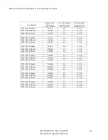
The gas supply should have a gas meter and regulator large enough to handle all of the gas appliances,
such as the furnace, hot water heater, and ovens, in operation at the same time. Add up all of the BTU
ratings to determine the total load. (See chart for supply requirements).
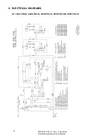
The electrical service should be three 20 amp 120V single phase circuits (2 poles with ground).
This provides a separate circuit breaker and single receptacle for each oven deck. The use of single
receptacles eliminates the possibility of plugging an additional device into oven circuit and will in most
jurisdictions eliminate need for a ground fault receptacle. If possible, leave room to the right of the
ovens for easy access and connection of gas and electric lines. The electrical outlets (Item 1) can also
be located to the left of the gas line. The oven electrical plugs are the NEMA 5-15 straight blade type
with 8 foot long cords
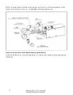
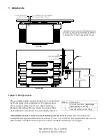
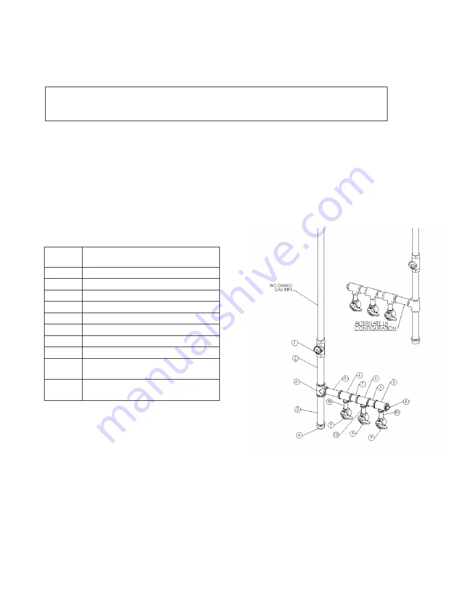
Figure 18: Gas Service view
The picture above shows a close-up detail of the gas service. 3/4" gas hose assemblies with quick
disconnects for each oven deck will be installed at each valve (item 9) during the oven setup and
installation. Alternatively, items 5-10 can be assembled to the left instead of to the right, as shown in
the upper right of the figure.
Item
No.
Description
1
1-1/2" Shut-Off Valve (1)
2
1-1/2" Pipe Nipple (2)
3
1-1/2" Pipe Tee (1)
4
1-1/2" Pipe Cap (1)
5
1-1/2" Pipe Nipple (1)
6
1-1/2" x ¾" x 1-1/2" Reducing Tee
(3)
7
1-1/2" Pipe Nipple (2)
8
1-1/2" Pipe Plug (1)
9
¾" Shut-Off Valve
(1 required for each oven)
10
¾" Pipe Nipple
(1 required for each oven)
CAUTION: Do not use Teflon tape on gas line connections as this can possibly cause
gas valve malfunction or plugging of orifices from shreds of tape. Use of Teflon tape
may affect warranty.


