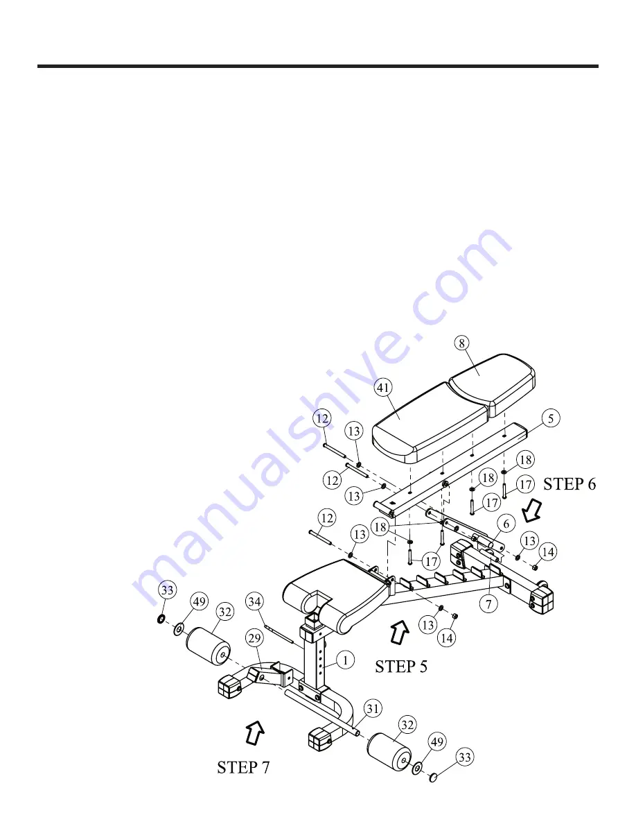
NOTE: Hand tighten bolts and Nylon Lock nuts until machine is fully assembled.
Step 5
Attach the Upper Back Pad (#8) & Lower Back Pad (#41) to Back Pad Support Frame (#5) using:
•
four M10*70 Button Head Cap Screw (#17)
•
fo
ur Φ11*Φ23*2
Flat Washer (#18)
Attach the Back Pad Support Frame (#5) to Main Frame (#1) using:
• one M12*125 Button Head Cap Screw (#12)
•
t
wo Φ13*Φ26*2
F
lat Washer (#13)
• one M12 Nylon Lock Nut (#14)
Step 6
Attach the Adjustable Back Pad Frame (#6) to Bac
k Pad Support Frame (#5) using:
• one M12*125 Button Head Cap Screw (#12)
•
t
wo Φ13*Φ26*2
F
lat Washer (#13)
• one M12 Nylon Lock Nut (#14)
Attach the Nylon Spacer (#7) to Adjustable Back P
a
d Frame (#6) u
sing:
• one M12*125 Button Head Cap Screw (#12)
•
t
wo Φ13*Φ26*2
F
lat Washer (#13)
• one M12 Nylon Lock Nut (#14)
Step 7
Attach the Foam Tube (#31) into Front Weight
Slide
Holder (#29). Place Foam Padding (#32)
on each side of Foam Tu
be (#31)-
secure with
P
lastic Washer (#49) & Me
t
al End Cap (#33).
Attach Front Weight Slide Holder (#29) to Main
Frame (#1) using L P
in (#34).
Note: Wrench tighten bolts and
Nylon Lock nuts.
7
Assembly
Summary of Contents for XM100
Page 1: ...4381 Adjustable FID Bench XM100...
Page 2: ...Table Of Contents 3 Important Safety Information Assembly 4 7 Parts List 8 Exploded View 9 2...
Page 4: ...Assembly 4...
Page 9: ...Exploded View 9...
Page 10: ......


