5
NOTE: Hand tighten bolts and locknut until machine is fully assembled.
STEP 1
STEP 2
Assembly
23
23
23
23
10
33
41
9 20
1
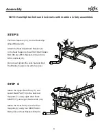
Attach the U-Shaped Front Base (2)
to the front part of the Main Frame (1),
and secure with three M10 washers (39),
three M10X15 Allen Bolts (31).
Insert the Rear Base (3) into the rear
part of the Main Frame (1) with two
M10X15 Allen Bolts (31) and two
M10 Washers (39).
Pull the Pop Pin (20) as far as it will
go and slide Sliding Block (9) onto
Incline Adjustment Tube (10). Push
two Spacers (23) into the Sliding Block
(9).
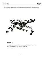
Push two Spacers (23) into the Incline
Adjustment Tube (10).Then attach Incline
Adjustment Tube (10) to the bracket on
the Main Frame (1). Secure with one M10X75
Allen Bolt (33) and one M10 Lock Nut (41).
Push four Spacers (23) into the Main
Frame (1) as illustrated.
23
23
23
23
2
39
39
31
31
31
33
41
1
3
31
31
39
39

