background image

NOTE: Hand tighten bolts and locknuts until machine is fully assembled.

           Lock nuts may require additional force to tighten completely.

Assembly

5

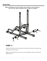
STEP 3 

Install the Sit-up Bar (8) into the bracket on the Lower Cross Brace (7) and secure with 
two Ring Head Lock Pins (24).

Slide the Foam Rollers (23) onto each end of the Sit-up Bar (8) and secure with Foam 
Roller Caps (10).

24

8

7

10

10

23

23

Summary of Contents for XM-4432

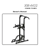
Page 1: ...Owner s Manual XM 4432 POWER TOWER ...

Page 2: ... 35 and or persons with pre existing health problems It is the owner s responsibility to ensure that all users of this unit have read the Owner s Manual and are familiar with safety information and precautions This unit should only be used on a level surface and is intended for indoor use only XMARK Fitness recommends an equipment mat be placed under the unit to protect the floor or carpet and for...

Page 3: ... Lower Upright 6 with Square Bracket 5 three M10x70 Bolts A2 and three M10 Lock Nuts C1 Repeat to complete the assembly for the Right Base 1 the Lower Support 4 and the Lower Upright 6 on the right side not shown Connect Left Base 2 and Right Base 1 with Bottom Brace 9 securing with four M10 x 70 Connect the Lower Uprights 6 with the Lower Cross Brace 7 and two Square Brackets 5 using four M10 x 7...

Page 4: ...uire additional force to tighten completely Assembly 5 STEP 3 Install the Sit up Bar 8 into the bracket on the Lower Cross Brace 7 and secure with two Ring Head Lock Pins 24 Slide the Foam Rollers 23 onto each end of the Sit up Bar 8 and secure with Foam Roller Caps 10 24 8 7 10 10 23 23 ...

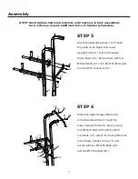
Page 5: ...s fully assembled Lock nuts may require additional force to tighten completely Assembly A1 A1 A1 A1 B1 B1 B1 B1 6 6 11 11 STEP 4 6 Insert the Upper Upright Tubes 11 to the Lower Upright Tubes 6 and secure with four M10x20 Bolts A1 and four M10 Washers B1 ...

Page 6: ...ttach the Extended Arms 13 through the joints of the Upper and Lower Upright Tubes 11 6 to the Upper Cross Brace 12 Secure them with four M10x20 Bolts A1 two M10x70 Bolts A2 and two M10 Lock Nuts C1 Attach the Upper Support Bars 14 to the Extended Arms 13 and the Lower Upright Tubes 6 Secure using four M10x70 Bolts A2 and four M10 Lock Nuts C1 Attach the Pull up Bar 18 to the Upper Upright Tubes 1...

Page 7: ...ly il Assembly 13 12 19 13 Congratulations You have completed assembly of your XM 4432 Attach one Arm Pad 19 to one Extended Arm 13 and secure with two M8x70 Bolts A4 and two M8 Washers B2 Repeat this step to complete the assembly for the other side Attach the Back Pad 20 to the Upper Cross Brace 12 and secure with two M8x40 Bolts A5 and two M8 Washers B2 ...

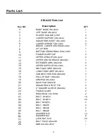
Page 8: ...ROSS BRACE XM 4432 1 13 EXTENDED ARM XM 4432 2 14 UPPER SUPPORT XM 4432 2 15 MID FOAM GRIP XM 4432 4 16 LONG FOAM GRIP XM 4432 1 17 CONNECTIVE HEAD XM 4432 2 18 PULL UP BAR XM 4432 1 19 ARM PAD XM 4432 2 20 BACK PAD XM 4432 1 21 SQUARE END FOOT F50 4 22 2 SQUARE SLEEVE XM 4432 2 23 FOAM ROLLER 2 24 RING HEAD LOCK PIN 2 A1 BOLT M10X20 16 A2 BOLT M10X70 20 A3 BOLT M10X55 2 A4 BOLT M8X70 4 A5 BOLT M8...

Page 9: ...A5 B2 B2 B2 B2 B2 B2 12 20 3 3 3 3 19 19 13 13 A4 A4 22 22 A2 A2 A2 A2 C1 C1 C1 C1 C1 C1 14 14 6 C1 C1 C1 C1 C1 C1 C1 C1 C1 C1 7 8 23 23 10 10 9 A2 A2 A2 A2 A2 A2 A2 A2 A2 B1 B1 B1 B1 A1 A 1 A1 2 21 24 15 15 21 21 21 A6 A6 B2 B2 5 5 6 1 A1 A1 A1 B1 B1 A1 A1 A1 B1 B1 A1 4 4 5 ...

Reviews: