7
NOTE: Hand tighten bolts and locknuts until machine is fully assembled.
Lock nuts may require additional force to tighten completely.
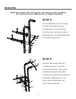
STEP 5
STEP 6
Assembly
C1
C1
13
13
A1
A1
A1
A1
A2
12
11
11
6
6
A2
A2
A2
A2
A3
18
B1
C1
C1
11
11
13
14
14
13
6
6
A3
B1
A2
A1
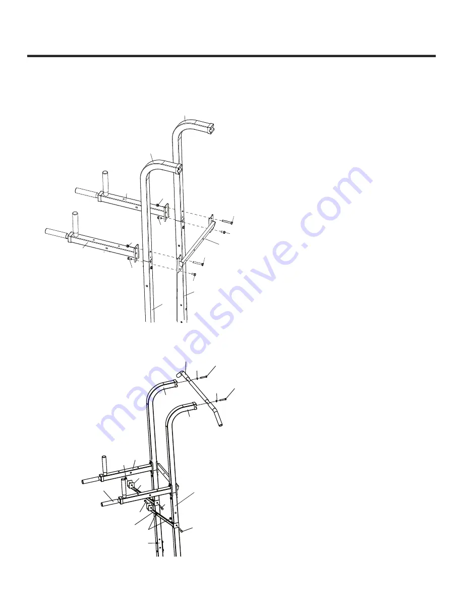
Attach the Extended Arms (13) through
the joints of the Upper and Lower
Upright Tubes (11 & 6) to the Upper
Cross Brace (12). Secure them with four
M10x20 Bolts (A1), two M10x70 Bolts (A2)
and two M10 Lock Nuts (C1).
Attach the Upper Support Bars (14)
to the Extended Arms (13) and the
Lower Upright Tubes (6). Secure using
four M10x70 Bolts (A2) and four M10
Lock Nuts (C1). Attach the Pull-up Bar (18)
to the Upper Upright Tubes (11) and
secure with two M10x55 Bolts (A3)
and two M10 Washers (B1).

