background image

XM-7617 Parts List

Ref #

Part #

Description

Qty

1
2
3
4
5
6
7
8
9

10
11
12
13
14
15
16
17
19
20
21
22
23
24
25
26
27
28
29
30
31
32
33
34
35

2
1
1
2
1
1
1
2
1
2
2
2
1
4
2
6
2

42

2
4
8
8
4

20

3
6
4
4

16
16

1
1
1
1

Upright Frame
Left Angle Support
Right Angle Support
Elbow Pad Support Frame
Back Pad Support Frame
Right Chin-Up Bar
Left Chin-Up Bar
Base Frame
Cross Frame
Elbow Pad
Small Plate
Big Plate
Back Pad
Plug 32
Grip
Grip
Plug 50.8*76.2

Flat Washer Φ11*Φ23*2

Bolt Cap

Big Washer Φ11*Φ30*2

Button Head Cap Screw M10*75
Button Head Cap Screw M10*80
Button Head Cap Screw M10*100
Nylon Locknut M10
Plug 50.8
Button Head Cap Screw M10*72
Foot Cap, Right 50.8*76.2 XM Series
Foot Cap, Left 50.8*76.2 XM Series
Button Head Cap Screw M8*25

Flat Washer Φ9*Φ22*2

Hex Key S=6
Wrench 17-19
Bolt Pack, XM-7617
Owner's Manual XM-7617

P00081
P00502
P00503
P00082
P00504
P00505
P00506
P00312
P00507
P00083
P00667
P00508
P00084
P00018
P00509
P00510
P00249
P00032
P00557
P00033
P00612
P00613
P00589
P00561
P00183
P00611
P00152
P00155
P00636
P00037
P00560
P00022
H00020
M00025

Parts List

11

Summary of Contents for XM-7617

Page 1: ...Owner s Manual XM 7617 POWER TOWER...

Page 2: ...Table of Contents 2 3 4 5 10 Important Safety Information Before You Start Assembly Parts List Exploded View 11 12...

Page 3: ...read the Owner s Manual and are familiar with safety information and precautions This unit should only be used on a level surface and is intended for indoor use only XMARK Fitness recommends an equipm...

Page 4: ...unit a part of your exercise program XMARK Fitness assures the very best in value appearance durability and biomechanics XMARK FITNESS SERIES This manual will guide you through the assembly process If...

Page 5: ...Assembly 5...

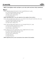
Page 6: ...nd Nylon Lock nuts until machine is fully assembled Step 1 Connect Upright Frame 1 to Base Frame 8 using one M10 75 Button Head Cap Screw 22 two 11 23 2 Flat Washer 19 one M10 Nylon Locknut 25 Repeat...

Page 7: ...le Supports 2 3 to Base Frame 8 and Cross Frame 9 using four M10 80 Button Head Cap Screw 23 eight 11 23 2 Flat Washer 19 four M10 Nylon Locknut 25 Connect Left and Right Angle Supports 2 3 to Upright...

Page 8: ...Assembly Step 2 8...

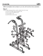
Page 9: ...and Nylon Lock nuts until machine is fully assembled Step 3 Connect Elbow Pad Support Frame 4 to Upright Frame 1 using four M10 100 Button Head Cap Screw 24 four 11 23 2 Flat Washer 19 four Big Washe...

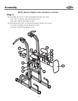
Page 10: ...s Step 4 Connect Back Pad 13 to Back Pad Support Frame 5 using two M10 72 Button Head Cap Screw 27 two 11 23 2 Flat Washer 19 Connect Elbow Pads 10 to Elbow Pad Support Frames 4 using four M10 72 Butt...

Page 11: ...8 76 2 Flat Washer 11 23 2 Bolt Cap Big Washer 11 30 2 Button Head Cap Screw M10 75 Button Head Cap Screw M10 80 Button Head Cap Screw M10 100 Nylon Locknut M10 Plug 50 8 Button Head Cap Screw M10 72...

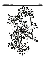
Page 12: ...Exploded View 12...

Page 13: ...Customer Service 1 800 719 4605...

Reviews: