Assembly
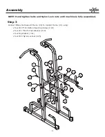
NOTE: Hand tighten bolts and Nylon Lock nuts until machine is fully assembled.
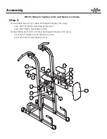
Step 2
Connect Back Pad Support Frame (#5) to both Upright Frames (#1) using:
•
four M10*80 Button Head Cap Screw (#23)
• eight Φ11*Φ23*2 Flat Washer (#19)
• four M10 Nylon Locknut (#25)
• two Small Plates (#11)
NOTE: Small Plates (#11) are to be placed on the outside of the machine.
Connect Left and Right Angle Supports (#2, #3) to Base Frame (#8) and Cross Frame (#9) using:
•
four M10*80 Button Head Cap Screw (#23)
• eight Φ11*Φ23*2 Flat Washer (#19)
• four M10 Nylon Locknut (#25)
Connect Left and Right Angle Supports (#2, #3) to Upright Frame (#1) using:
•
two M10*75 Button Head Cap Screw (#22)
• four Φ11*Φ23*2 Flat Washer (#19)
• two M10 Nylon Locknut (#25)
Connect Right and Left Chin-Up Bars (#6, #7) to Upright Frames (#1) using:
•
four M10*75 Button Head Cap Screw (#22)
• eight Φ11*Φ23*2 Flat Washer (#19)
• four M10 Nylon Locknut (#25)
• two Bolt cap (#20)
• two Big Plates (#12)
NOTE: Big Plates (#12) are to be placed on the outside of the machine.
7
Summary of Contents for XM-7617
Page 1: ...Owner s Manual XM 7617 POWER TOWER...
Page 5: ...Assembly 5...
Page 8: ...Assembly Step 2 8...
Page 12: ...Exploded View 12...


