xcore.ai Multichannel Audio Board 1v1 Hardware Manual
10
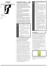
MIDI input and output
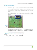
MIDI input and output is provided on the board via standard 5-pin DIN connectors compli-
ant to the MIDI specification.
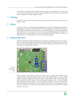
The MIDI signalling is essentially a 31.25kbaud UART over a 5mA current loop. The
interface circuits on this board are compliant with the MIDI specification addendum
pertaining to use with 3.3V logic signalling “MIDI 1.0 Electrical Specification Update 1.1
[2014]”.
The 3.3V logic signals are connected directly to ports on xcore.ai. A pullup resistor is used
to ensure the MIDI output does not drive when the xcore.ai device is not actively driving
the output.
Figure 14:
MIDI
input/output
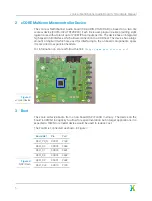
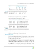
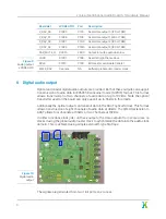
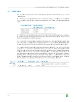
The MIDI input signal is connected to a 1-bit port on xcore.ai, the MIDI output signal is
driven by bit 0 of a 4-bit port, the other bits of the port being unused. This is described in
Figure
Board Net
xCORE GPIO
Port
Description
MIDI_TX
X1D14
P4C0
MIDI output signal
MIDI_RX
X1D13
P1F0
MIDI input signal
Figure 15:
MIDI xCORE
GPIO
12


