background image


Safety instructions 

1.Instructions 

Be sure to switch off the power supply before replacing or welding any components or inserting / 

plugging in connection wire 

Anti static measures to be taken (throughout the entire production process!): 

a)Do not touch here and there by hand at will; 

b) Be sure to use anti static electric iron; 

c) It’s a must for the welder to wear anti static gloves. 

Please refer to the detailed list before replacing components that have special safety requirements. Do 

not change the specs and type at will. 

2.Points for attention in servicing of LCD 

2.1 Screens are different from one model to another and therefore not interchangeable. Be sure to 

use the screen of the original model for replacement.   

2.2 The operation voltage of LCD screen is 700-825V. Be sure to take proper measures in 

protecting yourself and the machine when testing the system in the course of normal operation or right 

after the power is switched off. Please do not touch the circuit or the metal part of the module that is in 

operation mode. Relevant operation is possible only one minute after the power is switched off.   

2.3  Do not use any adapter that is not identical with the TV set. Otherwise it will cause fire or 

damage to the set. 

2.4    Never operate the set or do any installation work in bad environment such as wet bathroom, 

laundry, kitchen,or nearby fire source, heating equipment and devices or exposure to sunlight etc. 

Otherwise bad effect will result.   

2.5. If any foreign substance such as    water, liquid, metal slices or other matters happens to fall into 

the module, be sure to cut the power off immediately and do not move anything on the module lest it 

should cause fire or electric shock due to contact with the high voltage or short circuit. 

2.6. Should there be smoke, abnormal smell or sound from the module, please shut the power off at 

once. Likewise, if the screen is not working after the power is on or in the course of operation, the power 

must be cut off immediately and no more operation is allowed under the same condition.   

2.7. Do not pull out or plug in the connection wire when the module is in operation or just after the 

power is off because in this case relatively high voltage still remains in the capacitor of the driving 

circuit.Please wait at least one minute before the pulling out or plugging in the connection wire. 

2.8. When operating or installing LCD please don’t subject the LCD components to bending, twisting 

or extrusion, collision lest mishap should result.   

2.9 As most of the circuitry in LCD TV set is composed of CMOS integrated circuits, it’s necessary to 

pay attention to anti statics. Before servicing LCD TV make sure to take anti static measure and ensure 

full grounding for all the parts that have to be grounded.     

2.10.There are lots of connection wires between parts behind the LCD screen. When servicing or 

moving the set please take care not to touch or scratch them. Once they are damaged the screen would 

be unable to work and no way to get it repaired.   

2.11. Special care must be taken in transporting or handling it. Exquisite shock vibration may lead to 

Attention: This service manual is only for service personnel to take reference with. Before servicing

please read the following points carefully.     

Summary of Contents for LC-15H3

Page 1: ...COLOR TELEVISION LC 15H3 ...

Page 2: ...rouble shooting Method of software upgrading Brief introduction and working principle of L15H3 Wiring diagram Serial NO of parts Identification criteria for the bright spot and dark spot of the LCD screen Troubleshooting guide Schematic diagram 1 2 6 8 9 19 20 20 21 23 ...

Page 3: ...r other matters happens to fall into the module be sure to cut the power off immediately and do not move anything on the module lest it should cause fire or electric shock due to contact with the high voltage or short circuit 2 6 Should there be smoke abnormal smell or sound from the module please shut the power off at once Likewise if the screen is not working after the power is on or in the cour...

Page 4: ...displaying still picture in high brightness for a long time 3 Points for attention during installation 3 1 The front panel of LCD screen is of glass Wheng installing it please make sure to put it in place 3 2 For service or instatallation it s necessary to use specified screw lest it should damage the screen 3 3 Be sure to take anti dust measures Any foreign substance that happens to fall down bet...

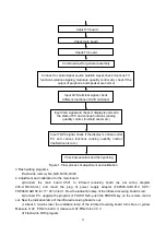
Page 5: ...ter the indication lamp of the infrared receiving board turns blue or yellow Measure L102 PIN2 to be5 0 V measure L107 PIN2 to be 3 3 V d Flash write DDC program Input YprPb signal check if the display is normal under PC and various functions analog quantity control line field center etc Check accessories and then packing Check main board Check TV board Combined test for general assembly Connect t...

Page 6: ...mperature so that x 270 y 283 red color temperature is constant as128 g Exit from the factory menu and enter route RGB Input 60Hz pane signal C_Hat_16x12 W through port VGA Enter the user menu and adjust the brightness to 50 and contrast to 50 Adjust the line center and the field center so that the picture is correctly positioned h Input signal of 16 gray grades Gray H 16 Enter the factory menu an...

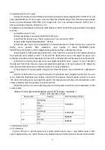
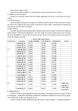
Page 7: ...ge clock MHz H SYNC kHz V SYNC Hz remark 640x480 60 25 175 31 469 59 900 720x400 70 28 322 31 469 70 086 800x600 60 40 000 37 879 60 317 1024x768 60 65 000 48 363 60 004 640x480 75 31 500 37 500 75 000 800x600 75 49 500 46 875 75 000 15 1024x768 75 78 750 60 023 75 029 640x480 60 25 175 31 469 59 900 720x400 70 28 322 31 469 70 086 800x600 60 40 000 37 879 60 317 1024x768 60 65 000 48 363 60 004 6...

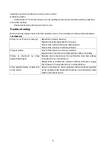
Page 8: ...k if the outdoor antenna is disconnected Check if the antenna is correctly oriented Fringe in picture Check if the antenna is correctly oriented Maybe there is electric wave reflected from hilltop or building Picture is interfered by stripe shaped bright spots Possibly due to interference from automobile train high voltage transmission line neon lamp etc Maybe there is interference between antenna...

Page 9: ...he liquid crystal TV set and make proper adjustment according to the signal types Picture too bright and there is distortion in the brightest area Check if the contrast setting is too high Possibly the output quality of DVD broadcaster is set too high It maybe also due to improper terminal connection of the video frequency signal in a certain position of the system Picture is whitish or too bright...

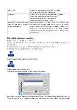
Page 10: ...remote control so as to enable the liquid crystal TV set to recheck the signal and then to display correct picture signal Method of software upgrading Steps of software upgrading are as follows 1 Select a serial connection wire and a VGA connection wire and then connect them by means of a patch panel 2 Use a serial wire to connect the PC to the patch panel and set TV set to off state 3 Open the so...

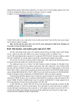
Page 11: ...ency signal undergoes an integrated tuner TUNER1 before a color full video signal is generated This video signal then enters analog board decoder IC N303 VCT3833 Pin19 where it is processed and it s output as analog signals R G B through Pin42 PIN43 PIN44 Audio frequency signal is processed with sound in IC N401 MSP3420G and then output through MSP3420G Pin28 Pin27 to SRS for surround sound proces...

Page 12: ...10 BLOCK DIAGRAM ...

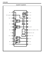
Page 13: ...d Ground Ground Ground VCC CTL H IN1 L IN2 Red 1 input Green 1 input Blue 1 input Red 2 input Green 2 input Blue 2 input VD 1 input VD 2 input VD output Blue output Composite sync output Composite video input Sync on Green Green output Red output HD output HD 2 input HD 1 input HD Sync signal detector BA7657F BA7657S ...

Page 14: ......

Page 15: ......

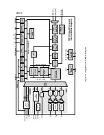
Page 16: ... GPIO PWM IR Decoder A 19 1 D 15 0 CS 1 0 2 Wire Serial Microprocessor Bus Memory Out Bus Memory Buffer Processor Memory Interface Memory In Bus OSD VYUV 7 0 VCLK VPEN PW130 ImageProcessor Internal Block Diagram ADC VIDEO PORTD 7 0 Sync Processing HS HSYNC VSYNC SOG Stripper SOGIN FILT PLL CLK R AIN G AIN B AIN A D Clamp A D Clamp VS Pow erOn Reset RESET Reset XI XO PLL and Oscillator MCLK DCLK UC...

Page 17: ......

Page 18: ......

Page 19: ......

Page 20: ...hift AFC Standard Supply ÏÏ ÏÏ ÏÏ L switch VCO 21 20 18 Loop filter 14 Ï Offset comp optional 26 FPLL 0 90 VIF amp 6 7 8 15 VIF CAGC CBL Take over point SIF input switch CAGC 22 12 4 9 16 13 Standard switch 23 VS Ï Ï 17 CRef Intercarrier FM NICAM 24 FM det AM det SIF amp 25 AF AM AFC Video 95 10851 Ï Video det Control ÏÏ ÏÏ 19 AFC switch Ï Ï ÏÏ Figure 1 Block diagram ...

Page 21: ...O IN Y Cb Cr 4ps X208 PW1306 4ps X602 9ps X203 9ps X102 5ps X603 30ps X204 8ps KEY BOARD back TOLCDPANEL Vout Lout Rout Vin Lin Rin AUDIO IN HEAD PHONE S VHS MSP3420 VCT3803 4ps X609 9ps X603 5ps X602 9ps X601 4ps X614 4ps X605 5ps X501 back or front IR BOARD back TUNER1 ANALOG BOARD DIGITAL BOARD wiringdiagram ...

Page 22: ...t is identified as a dark spot if it is dark in the state of white field and its dark size remains unchanged 4 Definition of two neighboring points Defects of a group of picture elements RB RG GB 15 17 20 Sell area America America Europe America LCD panel Samsung 335 15012 00 Samsung 335 17050 00 Chimei 335 2000F 00 Back light board 667 L15H3 14 667 L17H3 14 667 L20H3 14A High frequency board 667 ...

Page 23: ... signal Check whether U1 pin 11 have output waveform Check N8 pin3 pin 5 s input signal Replace N8 Yes No Yes No No No Yes No No 21 Troubleshooting guide No raster Does the logo appear on the screen when turning on the set Check whether the adapter supply 12V power to Digital Board Check whether X101 is properly inserted Check U125965V Check whether FUSE is melted Replace adapter Check whether U18...

Page 24: ...G B Hors Vers at X7 Check whether N1 has 5V power supply Check whether X9 pin 1 pin 2 have 5V power input Replace N2 Replace V105 V17 Replace N1 Measure N1 pin 33 pin 35 waveform Measure N1 pin 42 pin 44 waveform Check V105 V107 s output waveform No Yes Yes Yes No No No No No 22 ...

Page 25: ......

Page 26: ......

Page 27: ......

Page 28: ......

Page 29: ......

Reviews: