21
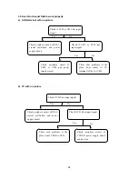
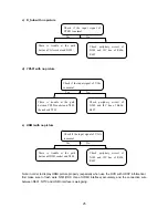
3.1 No raster, no picture and no sound
Note: The soldering quality of resistor rows between N101, N102 and N1 is very important, if it has
problem, DDR may fail to work properly.
No raster, no picture and no sound
Check Standby5V
Is the blue indicator
lights?
Disconnect the power supply board
with the data processing board, and
then measure Standby5V
Check if L508 is
rosin joint or short
to the ground
The power supply
board fails to
work properly
Check DDR, N141,
N142, G601 and
their voltage
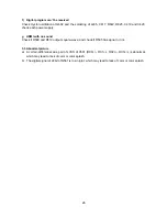
Check Z801,
N801 and V582
Check the capacitor
and resistor of N801
Check R748 is low
level or not, if
FU801 is 5V
Check DDR, N141, N142, G601 and
their voltages, the soldering of N1
Check if R571 is
square-wave
Check if N1 is rosin
joint
Check the periphery
circuit of N561
Is the power indicator lights?
No
Yes
Normal
Abnormal
Normal
Abnormal
Normal
Abnormal
Yes
No
No
Yes
Yes
No
Summary of Contents for LC-32FC18
Page 1: ...LCD TELEVISION LC 32FC18 America ...
Page 16: ...14 Block diagram of TPA3008D2 ...
Page 17: ...15 Pin description ...
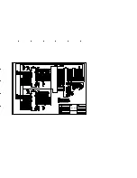
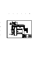
Page 29: ...CPU board ...
Page 30: ...CPU board ...
Page 31: ...CPU board ...
Page 32: ...CPU board ...
Page 33: ...CPU board ...
Page 34: ...CPU board ...
Page 35: ...CPU board ...
Page 36: ...CPU board ...
Page 37: ...CPU board ...
Page 38: ...CPU board ...
Page 39: ...AV trans connect board ...
Page 40: ...analog board ...
Page 41: ...32 power board 667 L32T18 20 ...
Page 43: ...APPENDIX Exploded view LC 32X18 ...
Page 45: ...603 L32FC18 14 Ver 1 1 ...

