1
5
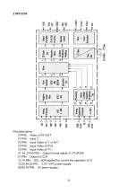
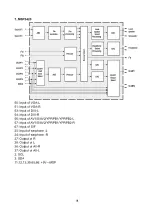
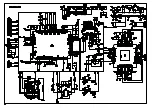
Pins description:
A12, A13: Input of VGA-R
A16, A17: Input of VGA-G
A20, A21: Input of VGA-B
P1, P2, N2, N3, M1-M4: Input of DVI-B
L1-L4, K2-K4, J1: Input of DVI-R
J2-J4, H1-H3, G1, G2: Input of DVI-G
AA2,AA3,Y1-Y3,N1-N3: Input of AV/TV/YPRPB-B
N4,V1-V4,U1-U3: Input of AV/TV/YPRPB-G
U4,T1-T4,R1-R3: Input of AV/TV/YPRPB-R
AB3: Input of DVI horizontal synchronizing
AB1: Input of DVI field synchronizing
G4: Input of DVI-CLK
F1: Input of DVI-DE
D6: Input of VGA horizontal synchronizing
P3: Input of VGA field synchronizing
F2: Input of AV/TV/YPRPB horizontal synchronizing
G3: Input of AV/TV/YPRPB field synchronizing
P4,AA4,AF12: Input of AV/TV/YPRPB-CLK
G6: Input of AV/TV/YPRPB-DE
AD13-15,AE13-15,AF14,AC15: Output of R
AF15,AC16,AD16,AE16,AD17,AE17,AF17,AC18: Output of G
AD18,AE18,AF18,AC19,AD19,AE19,AD20,AE20: Output of B
AE21: Output of horizontal synchronizing
AC21: Output of field synchronizing
AC13: Output of CLK
AF20: Output of EN
AD21: Output of EN VDD(power switch)
AF22: Output of EN BKL(back light switch)
B1: Output of PWW(back light adjustment)
F3, F4: SCL, SDA applied for control the operation of IC
B22,C22,D20,C21;H4;D21;AC8: 2.5V
D7;A5;A26;AF10: 3.3V
C10,D10-D19: JA2.5V1
C8,D8,D9: JA2.5V2
Summary of Contents for LC-40K17
Page 1: ...LC 40K17...
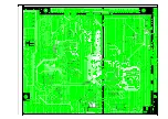
Page 27: ...Printed circuit boards top 25...
Page 28: ...bottom 26...
Page 29: ......
Page 30: ......
Page 31: ......
Page 32: ......
Page 33: ......
Page 34: ......
Page 35: ......
Page 36: ......
Page 37: ......
Page 38: ......
Page 39: ......
Page 40: ......
Page 41: ......
Page 42: ......
Page 43: ......
Page 44: ......
Page 45: ......
Page 46: ......
Page 47: ......
Page 48: ......
Page 49: ...EXPLODED VIEW...


