background image

Safety instructions 

1. Instructions


Be sure to switch off the power supply before replacing or welding any components   or 
inserting/plugging in connection wire Anti static measures to be taken (throughout the entire 
production process!): 
a) Do not touch here and there by hand at will; 
b) Be sure to use anti static electric iron; 
c) It’s a must for the welder to wear anti static gloves. 
Please refer to the detailed list before replacing components that have special safety requirements. 
Do not change the specs and type at will. 


2. Points for attention in servicing of LCD 

2.1 Screens are different from one model to another and therefore not interchangeable. Be sure to 
use the screen of the original model for replacement.   
2.2 The operation voltage of LCD screen is 700-825V. Be sure to take proper measures in 
protecting yourself and the machine when testing the system in the course of normal operation or 
right after the power is switched off. Please do not touch the circuit or the metal part of the module 
that is in operation mode. Relevant operation is possible only one minute after the power is 
switched off.   
2.3 Do not use any adapter that is not identical with the TV set. Otherwise it will cause fire or 
damage to the set.   
2.4 Never operate the set or do any installation work in bad environment such as wet bathroom, 
laundry, kitchen, or nearby fire source, heating equipment and devices or exposure to sunlight etc. 
Otherwise bad effect will result.   
2.5 If any foreign substance such as water, liquid, metal slices or other matters happens to fall into 
the module, be sure to cut the power off immediately and do not move anything on the module lest it 
should cause fire or electric shock due to contact with the high voltage or short circuit. 
2.6 Should there be smoke, abnormal smell or sound from the module, please shut the power off at 
once. Likewise, if the screen is not working after the power is on or in the course of operation, the 
power must be cut off immediately and no more operation is allowed under the same condition.   
2.7 Do not pull out or plug in the connection wire when the module is in operation or just after the 
power is off because in this case relatively high voltage still remains in the capacitor of the driving 
circuit. Please wait at least one minute before the pulling out or plugging in the connection wire. 
2.8 When operating or installing LCD please don’t subject the LCD components to bending, twisting 
or extrusion, collision lest mishap should result. 
2.9 As most of the circuitry in LCD TV set is composed of CMOS integrated circuits, it’s necessary 
to pay attention to anti statics. Before servicing LCD TV make sure to take anti static measure and 
ensure full grounding for all the parts that have to be grounded.


2.10 There are lots of connection wires between parts behind the LCD screen. When servicing or 
moving the set please take care not to touch or scratch them. Once they are damaged the screen 

Attention: 

This


service manual is only for service personnel to take reference with. Before 

servicing please read the following points carefully. 


Summary of Contents for LC-40K17

Page 1: ...LC 40K17...

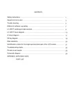
Page 2: ...7 working principle analysis LC 40K17 block diagram IC block diagram Wiring diagram Main assembly Identification criteria for the bright spot and dark spot of the LCD screen Troubleshooting charts Pri...

Page 3: ...will result 2 5 If any foreign substance such as water liquid metal slices or other matters happens to fall into the module be sure to cut the power off immediately and do not move anything on the mod...

Page 4: ...of picture residue on the screen as commonly called ghost shadow The extent of the residual picture varies with the maker of LCD screen This phenomenon doesn t represent failure This ghost shadow may...

Page 5: ...signal then select the mode item after that you can press enter to select three kinds of color temperature namely 6500K 9300K and 12000K press MENU to exit Note the white balance adjustment should be...

Page 6: ...until the value of the two levels gray scale be 308 and 316 Select 9300k of mode adjustment offset_R offset_G and offset_B let the color coordinate of the second level be 285 and 293 and its brightnes...

Page 7: ...scale signal of TIME392 480p TIME394 720p and TIME396 1080i separately repeat the above operations to let color coordinate of the second level be 285 and 290 and its brightness be about 3 5nit 4 Perfo...

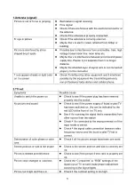
Page 8: ...hone 2 TV set Symptoms Possible cause Unable to switch the power on Check to see if the power plug has been inserted properly into the socket No picture and sound Check to see if the power supply of l...

Page 9: ...here is any obstruct between the remote control and the TV set Check if the remote control signal receiving window is exposed to strong fluorescence No picture and sound but only hash Check if the ant...

Page 10: ...w up after running the program Based on the computer features set up the serial port COM Port Select corresponding serial port if it s unable to FLASH WRITE change to another port Baud is selected to...

Page 11: ...to U12 also RGB signal of computer VGA RGB signal of 24BIT produced by DV1 through U15 TFP403 501 Do the picture format processing for the three kinds of signal in U12 Firstly do the A D conversion fo...

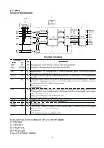
Page 12: ...V2 R L AV R L OUT U15 DVI DRIVER TFP403 U12 SCALER JAG ASM U29 VIDEO DECODER VPC3230 U30 ADC MST98 83 U13 DEINTER LACER FLI2310 U14 SDRAM U19 SDRAM U20 SDRAM U31 LVDS DRIVER DS90C383 U3 EEPROM NA01 AU...

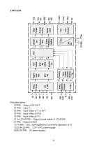
Page 13: ...2 9 PIN Output of Y 12 19 PIN Output of U 70 77 PIN Output of V 56 57 PIN SCL SDA applied for control the operation of IC 66 PIN Output of horizontal synchronizing 64 PIN Output of field synchronizin...

Page 14: ...IN Input Video of Y or AV1 74 PIN Input Video of AV2 75 PIN Input Video of TV 31 34 37 40 PIN Output format signal of ITU R656 27 PIN Output of CLK 13 14 PIN SCL SDA applied for control the operation...

Page 15: ...V 29 32 35 38 40 PIN Input of Y 1 PIN Input of YPRPB horizontal synchronizing 2 PIN Input of YPRPB field synchronizing 4 PIN Input of YPRPB CLK 5 PIN Input of YPRPB DE 195 PIN Input of AV TV CLK 114...

Page 16: ...l synchronizing 119 PIN Output of field synchronizing 120 PIN Output of DE 45 46 PIN SCL SDA applied for control the operation of IC 8 62 112 193 171 187 PIN 3 3V power supply 155 168 16 68 123 197 PI...

Page 17: ...d synchronizing F2 Input of AV TV YPRPB horizontal synchronizing G3 Input of AV TV YPRPB field synchronizing P4 AA4 AF12 Input of AV TV YPRPB CLK G6 Input of AV TV YPRPB DE AD13 15 AE13 15 AF14 AC15 O...

Page 18: ...e time of active video display versus nonactive display or blank time During blank only HSYNC VSYNC and CTL1 2 are transmitted During times of active display or nonblank only pixel data QE 23 0 and QO...

Page 19: ...izontal synchronizing 6 38 82 91 18 29 57 78 97 3 3V power supply 6 DS90C383 51 52 54 56 3 50 2 Input of R 4 6 7 11 12 14 8 10 Input of G 15 19 20 22 24 16 18 Input of B 27 Input of horizontal synchro...

Page 20: ...I L 54 Input of DVI R 56 Input of AV1 S AV2 YPRPB1 YPRPB2 L 57 Input of AV1 S AV2 YPRPB1 YPRPB2 R 67 Input of SIF 25 Input of earphone L 24 Input of earphone R 27 Output of R 28 Output of L 36 Output...

Page 21: ...h t p a n e l T o s p e a k e r T o e a r p h o n e 6 6 6 L 4 0 K 1 7 N 4 0 A Vp r o c e s s in gb o a rd T ok e y b o a rd T or e m o tec o n tr o l 6 6 7 L 4 0 K 1 7 N 5 6 C P Ub o a rd T o pp a n...

Page 22: ...53 0JAG0 00 FLI2310 353 23100 00 TFP403PZP 353 04030 10 VPC3230D 353 32300 80 MST9883B 353 98830 10 DS90C385 353 03830 70 TSC80251G2D 353 80251 10 AT49F002NT 352 49002 70 IR board 667 L37K7 09 Keypad...

Page 23: ...mm 5mm Total defected point 8 7 5 4 Notes 1 Definition of defected point bright spot dark spot It is identified as a defected point if its area exceeds 1 2 of a single picture element R G B 2 Definiti...

Page 24: ...heck the indicator in turn on condition Check if the indicator is flicker in the sensor control normal condition Check if the CN2 output 24V Check if the PIN26 30 of P4 is 5V Check if it s melted of F...

Page 25: ...nels Replacing CPU board Testing power supply 12V of video processing board Replacing power supply board Check if PIN2 1VPP signal and noise wave of P32 Replacing TUNER01 Check if PIN56 15 734KHz sync...

Page 26: ...PIN5 and PIN8 output wave of NA03 Check PIN27 and PIN28 output wave of NA01 Check PIN67 wave of NA01 Replacing TUNA01 Replacing NA04 Replacing NA03 Replacing NA01 no yes no yes yes yes no no Check if...

Page 27: ...Printed circuit boards top 25...

Page 28: ...bottom 26...

Page 29: ......

Page 30: ......

Page 31: ......

Page 32: ......

Page 33: ......

Page 34: ......

Page 35: ......

Page 36: ......

Page 37: ......

Page 38: ......

Page 39: ......

Page 40: ......

Page 41: ......

Page 42: ......

Page 43: ......

Page 44: ......

Page 45: ......

Page 46: ......

Page 47: ......

Page 48: ......

Page 49: ...EXPLODED VIEW...

Page 50: ...17 Pin cover 808 10800 AW1 18 Stand 615 10517 00 19 Stand cover 808 10799 AWO 20 AV cover 808 10798 AWO 21 Screw cap 785 20023 00 22 AV cover 808 10796 AWO 23 Connect piece cover 808 10808 AWO 24 Con...

Page 51: ...NO DESCRIPTION PART 41 Infrared receiver assy 667 L37K7 09 42 USB baffle 808 1A801 AWO 43 Earphone assy 667 L37K7 10 44 LED column 700 60196 100 45 LED column 700 60200 00...

Page 52: ...0002 422 VIDEO LINE YELLOW WHITE RED 665 D0002 572 LVDS LINE 30 PINS230mm 700 60196 100 LED COLUMN MOLD TRANSPARENT GREY 0A 700 60200 00 LED COLUMN 770 471C0 70 ULXT 20 470mm RED BLACK 770 471C0 70 UL...

Page 53: ...W B M3X8 D Zn 852 33008 87 SCREW B M3X8 D Zn BLACK 852 33008 87 SCREW B M3X8 D Zn BLACK 852 33008 87 SCREW B M3X8 D Zn BLACK 852 33008 87 SCREW B M3X8 D Zn BLACK 852 33008 87 SCREW B M3X8 D Zn BLACK 8...

Page 54: ...EW SJ2836 M3X8 D Zn 852 93008 81 COMPOSE SCREW SJ2836 M3X8 D Zn 852 94008 87 COMPOSE SCREW SJ2836 M4X8 D Zn BLACK 852 94008 87 COMPOSE SCREW SJ2836 M4X8 D Zn BLACK 862 20039 00 CARTON CLIPS 863 81052...

Page 55: ...UE 700X4X1 808 70366 00 EVA GLUE 610X4 5X4 5 851 13008 34 SCREW P T3 8BT Y 851 13008 34 SCREW P T3 8BT Y 851 23010 14 SCREW SJ2824 ST3X10C Y 851 23010 14 SCREW SJ2824 ST3X10C Y 851 24010 34 SCREW SJ28...

Page 56: ...0 39 JL 467 2G047 H0 METAL RESISTOR 2W 47 JL 467 2G368 H0 METAL RESISTOR 2W 68K JL 467 4E022 H0 FUSIBLE RESISTOR 1 2W 22 JL 467 8E510 H0 SOLID RESISTOR 1 2W 1M JL 467 8E539 H0 SOLID RESISTOR 1 2W 3 9...

Page 57: ...OR RC11 1 8W 2K J R555 455 22233 H0 SMD RESISTOR RC11 1 8W 3 3K J R527 455 22268 H0 SMD RESISTOR RC11 1 8W 6 8K J R515 455 22310 H0 SMD RESISTOR RC11 1 8W 10K J R521 455 22310 H0 SMD RESISTOR RC11 1 8...

Page 58: ...A05 364 32101 00 2 PINS CONNECTORS TJC3 02A XA09 364 34101 00 4 PINS CONNECTORS TJC3 04A XA10 364 34101 00 4 PINS CONNECTORS TJC3 04A XA12 364 341AY 00 4 PINS CONNECTORS JC10 4A XA04 364 41207 00 ANTE...

Page 59: ...65 N0300 00 COAXIAL CABLE CSYV 2B 300 666 13001 00 FERRITE BEAD TY30X20X10 666 13501 0G FERRITE BEAD 3 5X1X6 L1 666 13501 0G FERRITE BEAD 3 5X1X6 L2 667 L37K7 40 AUDIO VIDEO PROCESSING BOARD ASS Y MAN...

Page 60: ...9 455 12410 H0 SMD RESISTOR FTR0603104JR RA50 455 12412 H0 SMD RESISTOR FTR0603124JR RA56 455 12412 H0 SMD RESISTOR FTR0603124JR RA57 455 12412 H0 SMD RESISTOR FTR0603124JR RA59 455 22110 H0 SMD RESIS...

Page 61: ...SMD CAPACITOR 0603CG510J500BA CA02 456 3051H 11 SMD CAPACITOR 0603CG510J500BA CA03 456 3122H 11 SMD CAPACITOR 0603CG221J500BA CA10 456 3122H 11 SMD CAPACITOR 0603CG221J500BA CA26 456 3147H 11 SMD CAPA...

Page 62: ...500 BUTTON PCB 360 10013 00 TACT SWITCH K66T 1 2 0 BL 1 5 S1 360 10013 00 TACT SWITCH K66T 1 2 0 BL 1 5 S2 360 10013 00 TACT SWITCH K66T 1 2 0 BL 1 5 S3 360 10013 00 TACT SWITCH K66T 1 2 0 BL 1 5 S4 3...

Page 63: ...LECTROLYTIC CAPACITOR CD110 16V 1000uF M C200 464 6D810 M1 ELECTROLYTIC CAPACITOR CD110 16V 1000uF M C382 464 6D810 M1 ELECTROLYTIC CAPACITOR CD110 16V 1000uF M C469 464 6D810 M1 ELECTROLYTIC CAPACITO...

Page 64: ...IC SN74AHC14PWP D U17 353 74140 30 SMD IC SN74AHC14PWP D U7 353 74320 40 SMD IC SN74AHC32PWP D U6 353 80251 10 SMD ICTSC80251G2D 16CB D U2 353 86229 10 SMD ICZ8622912SSC M U32 353 98830 30 SMD IC MST...

Page 65: ...CDPS 16V 10uF M C486 454 04610 MA SMD ELECTROLYTIC CAPACITOR CDPS 16V 10uF M C487 454 04610 MA SMD ELECTROLYTIC CAPACITOR CDPS 16V 10uF M C497 454 04610 MA SMD ELECTROLYTIC CAPACITOR CDPS 16V 10uF M C...

Page 66: ...0 H0 SMD RESISTOR FTR0603000XR R124 455 12000 H0 SMD RESISTOR FTR0603000XR R131 455 12000 H0 SMD RESISTOR FTR0603000XR R132 455 12000 H0 SMD RESISTOR FTR0603000XR R194 455 12000 H0 SMD RESISTOR FTR060...

Page 67: ...750FR R19 455 12075 H0 SMD RESISTOR FTR0603750JR R303 455 12075 H0 SMD RESISTOR FTR0603750JR R304 455 12075 H0 SMD RESISTOR FTR0603750JR R305 455 12075 H0 SMD RESISTOR FTR0603750JR R306 455 12075 H0 S...

Page 68: ...181JR R49 455 12143 H0 SMD RESISTOR FTR0603431JR R209 455 12147 H0 SMD RESISTOR FTR0603471JR R214 455 12147 H0 SMD RESISTOR FTR0603471JR R217 455 12147 H0 SMD RESISTOR FTR0603471JR R218 455 12147 H0 S...

Page 69: ...3103JR R298 455 12310 H0 SMD RESISTOR FTR0603103JR R309 455 12310 H0 SMD RESISTOR FTR0603103JR R310 455 12310 H0 SMD RESISTOR FTR0603103JR R35 455 12310 H0 SMD RESISTOR FTR0603103JR R388 455 12310 H0...

Page 70: ...SMD CAPACITOR C1608Y5V1E104ZT C112 456 2410R C1 SMD CAPACITOR C1608Y5V1E104ZT C115 456 2410R C1 SMD CAPACITOR C1608Y5V1E104ZT C117 456 2410R C1 SMD CAPACITOR C1608Y5V1E104ZT C118 456 2410R C1 SMD CAPA...

Page 71: ...C18 456 2410R C1 SMD CAPACITOR C1608Y5V1E104ZT C180 456 2410R C1 SMD CAPACITOR C1608Y5V1E104ZT C181 456 2410R C1 SMD CAPACITOR C1608Y5V1E104ZT C182 456 2410R C1 SMD CAPACITOR C1608Y5V1E104ZT C183 456...

Page 72: ...04ZT C377 456 2410R C1 SMD CAPACITOR C1608Y5V1E104ZT C379 456 2410R C1 SMD CAPACITOR C1608Y5V1E104ZT C381 456 2410R C1 SMD CAPACITOR C1608Y5V1E104ZT C393 456 2410R C1 SMD CAPACITOR C1608Y5V1E104ZT C39...

Page 73: ...C93 456 2410R C1 SMD CAPACITOR C1608Y5V1E104ZT C94 456 2410R C1 SMD CAPACITOR C1608Y5V1E104ZT C96 456 2410R C1 SMD CAPACITOR C1608Y5V1E104ZT C97 456 2410R C1 SMD CAPACITOR C1608Y5V1E104ZT C98 456 2410...

Page 74: ...SMD CAPACITOR 0603CG152J500BA C237 456 3215H 11 SMD CAPACITOR 0603CG152J500BA C256 456 3215H 11 SMD CAPACITOR 0603CG152J500BA C387 456 3215H 11 SMD CAPACITOR 0603CG152J500BA C388 456 3282K B1 SMD CAP...

Page 75: ...D BG2012B300T L21 666 12012 00 SMD FERRITE BEAD BG2012B300T L22 666 12012 00 SMD FERRITE BEAD BG2012B300T L24 666 12012 00 SMD FERRITE BEAD BG2012B300T L25 666 12012 00 SMD FERRITE BEAD BG2012B300T L6...

Page 76: ...SMD FERRITE BEAD STPB3216 380PT FB60 666 13207 00 SMD FERRITE BEAD STPB3216 380PT FB7 666 13207 00 SMD FERRITE BEAD STPB3216 380PT FB74 666 13207 00 SMD FERRITE BEAD STPB3216 380PT FB75 666 13207 00 S...

Reviews: