3
Alignment instructions
1. Test equipment
Digital multimeter, signal generator (54200)
PC set (FLASH writing programs and W24CXX.EXE have to be installed first,)
VG849 (HDMI signal generator)
CA210 (White balancer), DVD player(with HDMI output), monitor
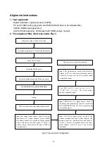
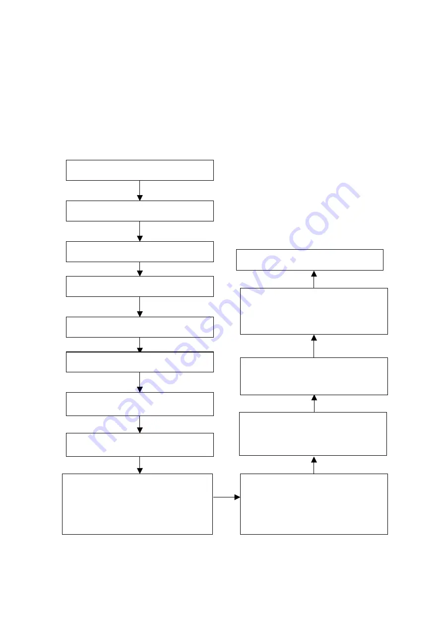
2. The alignment flow chart (see below Fig.1)
Fig.1 Flow process of alignment
Check accessories and then packing
Write N105, N403, N607, N70, N606
To produce main board, TV board and other board
Check the MAIN board
Check the buttons board and IR receive board
Combined test for general assembly
Input AV1/S/AV2 signal source, check if the
various terminal functions (system identify and
analog control etc.) and the picture and sound of
AV-out is normal. (S-terminal shares the same
audio channel with AV1, and it can be auto
identified)
Check the TV board
Input YPbPr/YCbCr 1/2 signal source; check if
the picture and sound analog control is normal in
the COMPONENT state. The AV-out output sound
is originally signal
Input HDMI and DVI signal source, check if
the HDCP KEY is normal.
The AV-out output
sound is originally signal
Input VGA signal source, check is the display is
normal in PC state and various function (analog
control) H-V center etc. The AV-out output sound
is originally signal
Aging
Input the center signal source, check if various
functions of TV (search channel, system identify
and analog control etc.), earphone output, speaker
output and the picture and sound of AV-out is
normal. (check stereo/SAP, CCD and VCHIP for
American unit)
ADC correction and white balance adjustment
Summary of Contents for LC-40T7
Page 1: ...LCD TELEVISION LC 40T7...
Page 27: ...PDF pdfFactory Pro www fineprint com cn...
Page 28: ...PDF pdfFactory Pro www fineprint com cn...
Page 29: ...PDF pdfFactory Pro www fineprint com cn...
Page 30: ...PDF pdfFactory Pro www fineprint com cn...
Page 31: ...PDF pdfFactory Pro www fineprint com cn...
Page 32: ......
Page 33: ......
Page 34: ......
Page 35: ......
Page 36: ...42 Power board...
Page 37: ...603 L40T70 10 Ver 1 0...


