Summary of Contents for LC20H3D
Page 1: ...COLOR TELEVISION LC20H3D...
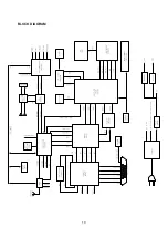
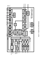
Page 12: ...10 BLOCK DIAGRAM...
Page 14: ......
Page 15: ......
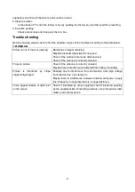
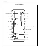
Page 17: ......
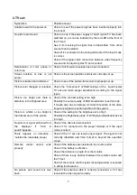
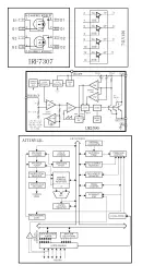
Page 18: ......
Page 19: ......
Page 25: ...1 2 3 4 5 6 7 8 9 101112 13 14 15 16 17 18 23 EXPLODED VIEW...
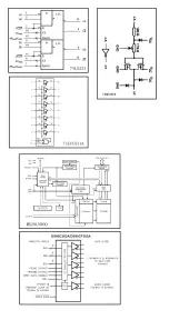
Page 44: ......
Page 45: ......
Page 46: ......
Page 47: ......
Page 48: ......
Page 49: ......
Page 50: ......
Page 51: ......
Page 52: ......
Page 53: ......
Page 54: ......
Page 55: ......