background image

LCD

  TELEVISION

LC20Y19

Summary of Contents for LC20Y19

Page 1: ...LCD TELEVISION LC20Y19...

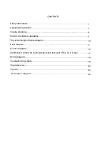
Page 2: ...software upgrading The unit working principle analysis Block diagram IC block diagram Identification criteria for the bright spot and dark spot of the LCD screen Wiring diagram Troubleshooting charts...

Page 3: ...will result 2 5 If any foreign substance such as water liquid metal slices or other matters happens to fall into the module be sure to cut the power off immediately and do not move anything on the mod...

Page 4: ...of picture residue on the screen as commonly called ghost shadow The extent of the residual picture varies with the maker of LCD screen This phenomenon doesn t represent failure This ghost shadow may...

Page 5: ...voltage to be 12v and 5v 3 3 main board adjustment 3 3 1 IF amplifier adjustment a Turn off the J201 J202 J203 J204 J205 and J5 input 38MHz PAL SYSTEM and 45 75MHz N Write memory N300 and N400 To pro...

Page 6: ...nate 0 293 0 008 g Repeat e step to f step it must be measure a true value h The unit without VGA interface of 20 N system you should be rework c step enter VIDEO channel input Gray H 16 for NTSC syst...

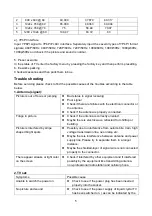
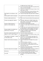
Page 7: ...electrical connector or the antenna Check if the antenna is properly connected Fringe in picture Check if the antenna is correctly oriented Maybe there is electric wave reflected from hilltop or buil...

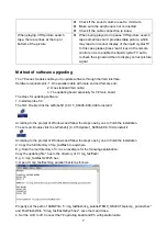
Page 8: ...system Picture is whitish or too bright in the darkest area of the picture Check if the setting for the brightness is too high Possibly the brightness grade of DVD player broadcaster is set too high N...

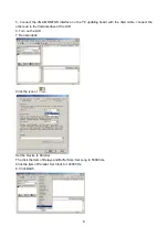
Page 9: ...board especially for Y main board The steps for updating software 1 Install Gprobe 5 0 The first Double click the GProbe5 1 0 0 15_S0006 EXE 09A to install it According to the prompt of Windows and f...

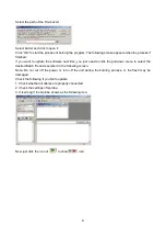
Page 10: ...VGA cable connect the other end to the VGA interface of the LCD 6 Turn on the LCD 7 Run Gprobe5 Click the icon of Set the Device to Parallel The click the item of Delays and Buffer Size Set Long to 50...

Page 11: ...just need to click the pull down menu to select the desired Batch file and execute it in the following screen Note Do not cut off the power or turn off the unit during the burning process or the flash...

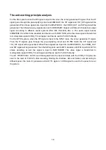
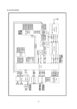
Page 12: ...sent to FLI8125 directly For the NTSC system when the RF signal is input to the NTSC tuner the turner generates IF signal Then the IF signals goes through the pre amplifying circuit and 45 75M SAW th...

Page 13: ...11 BLOCK DIAGRAM...

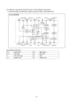
Page 14: ...e inner IC block diagram and function 1 Inner block diagram of M52760 IF signal processing IC AFT QIF VIDEO OUT Descriptions of the pins Pin Description Pin Description 4 5 VIF input 13 QIF OUT 7 1ST_...

Page 15: ...13 2 Inner block diagram of LA72700 stereo decoder...

Page 16: ...multi channel selector HEF4052BT while the audio signal from the AV inputs is sent to R2S15900SP directly After the processing of bass treble balance and AVL by R2S15900S all these processed audio sig...

Page 17: ...15 5 Inner block diagram of TPA1517 6W stereo audio amplifier...

Page 18: ...D_SEL_1 10 RESETn Reset 52 AUD_SEL_2 15 XTAL Resonator output 63 PBIAS Panel s oblique line control 16 TCLK Basic clock 64 PPWR Backlight adjustment 24 SCL_RS232 SCL_RS232 90 DEN Display data 25 SDA_R...

Page 19: ...mm 5mm Total defected point 8 7 5 4 Notes 1 Definition of defected point bright spot dark spot It is identified as a defected point if its area exceeds 1 2 of a single picture element R G B 2 Definiti...

Page 20: ...18 Wiring diagram Button board B Button board A Right speaker Left speaker Back light board Power board Main board indicator light board...

Page 21: ...ainboard Vcc 18V X702 1 2 12V 3 4 GND 5 6 18V 7 8 GND 9 PBIAS 10 PWM 1 No raster no picture and no sound When the main power is turned on the unit s indicator lights up in red red indicator is control...

Page 22: ...ent from the actual frequency Connect the signal cable manually adjust the frequency to conform to the actual frequency Enter into service menu check AFT value should be about 1 6V If the difference i...

Page 23: ...ce D502 Check whether pin1 of N501 has wave Replace N502 Check whether N502 is damaged Replace N505 Check whether N505 is damaged Check whether N505 D507 is damaged Replace the damaged parts Y Y Y N Y...

Page 24: ...EXPLODED VIEW 22...

Page 25: ...3 10219 3C0 14 REAR CABINET 780 P19WHP121 15 REAR CABINET COVER LEFT 808 60923 120 16 AXLETREE COVER 808 60925 120 17 CHASSIS ASSY DZ 2620 615 10593 01 18 REAR CABINET COVER RIGHT 808 60924 120 19 WAL...

Page 26: ...EEN 808 20359 222 PMMA 2H FACESILK SCREEN BLACK 808 60921 120 AV BAFFLE LEFT MOLD GREY G05 808 60922 120 AV BAFFLE RIGHT MOLD GREY G05 808 60923 120 BACK CABINET COVER BOARD LEFT MOLD GREY G05 808 609...

Page 27: ...4 10228 0G0 DECORATIVE NET SILVERY WHITE 06 870 10327 00 WALL MOUNT BRACKET 870 1A358 00 RF HOLDER 870 30209 120 SIDE AV BRACKET MOLD GREY G05 870 3A206 00 DECORATIVE NET HOLDER 870 3A208 120 SWITCH B...

Page 28: ...CTORS TJC3 12A X509 364 77511 00 FUSE HOLDER FU501 364 77511 00 FUSE HOLDER 459 6147K 00 CERAMIC CAPACITOR DE0705B471K1k C517 459 6147K 00 CERAMIC CAPACITOR DE0705B471K1k C518 459 6210K 00 CERAMIC CAP...

Page 29: ...6 T2501 01 HEAT SINK N501 775 60137 00 HOLLOW PILLAR 2 36 14B D512 775 60137 00 HOLLOW PILLAR 2 36 14B 808 70385 00 INSULATOR 851 13008 56 SCREW P T3X8S R 667 L20S19 20 POWER PCB ASS Y AUTOMATIC INSER...

Page 30: ...RESISTOR 1 6W 1K J R506 467 1C210 H03 CARBON RESISTOR 1 6W 1K J R510 467 1C210 H03 CARBON RESISTOR 1 6W 1K J R512 467 1C210 H03 CARBON RESISTOR 1 6W 1K J R515 467 1C215 H03 CARBON RESISTOR 1 6W 1 5K J...

Page 31: ...MD DIODE LL4148 D209 340 00001 0S SMD DIODE LL4148 L102 340 00001 0S SMD DIODE LL4148 L103 340 00296 00 SMD DIODE SK34 D702 342 01380 00 SMD TRANSISTOR BSS138LT1 V202 342 01380 00 SMD TRANSISTOR BSS13...

Page 32: ...0 SMD RESISTOR FTR0603000XR R733 455 12000 H0 SMD RESISTOR FTR0603000XR R739 455 12011 H0 SMD RESISTOR FTR0603110JR R207 455 12011 H0 SMD RESISTOR FTR0603110JR R208 455 12020 H0 SMD RESISTOR FTR060320...

Page 33: ...75 H0 SMD RESISTOR FTR0603750JR R359 455 12110 H0 SMD RESISTOR FTR0603101JR R155 455 12110 H0 SMD RESISTOR FTR0603101JR R156 455 12110 H0 SMD RESISTOR FTR0603101JR R220 455 12110 H0 SMD RESISTOR FTR06...

Page 34: ...SMD RESISTOR FTR0603332JR R701 455 12233 H0 SMD RESISTOR FTR0603332JR R715 455 12239 H0 SMD RESISTOR FTR0603392JR R242 455 12247 H0 SMD RESISTOR FTR0603472JR R125 455 12247 H0 SMD RESISTOR FTR0603472...

Page 35: ...RESISTOR FTR0603473JR R112 455 12347 H0 SMD RESISTOR FTR0603473JR R113 455 12347 H0 SMD RESISTOR FTR0603473JR R117 455 12347 H0 SMD RESISTOR FTR0603473JR R118 455 12347 H0 SMD RESISTOR FTR0603473JR R...

Page 36: ...PACITOR 06032E104M250BA C119 456 2410M C1 SMD CAPACITOR 06032E104M250BA C122 456 2410M C1 SMD CAPACITOR 06032E104M250BA C123 456 2410M C1 SMD CAPACITOR 06032E104M250BA C124 456 2410M C1 SMD CAPACITOR...

Page 37: ...ACITOR 06032E104M250BA C338 456 2410M C1 SMD CAPACITOR 06032E104M250BA C339 456 2410M C1 SMD CAPACITOR 06032E104M250BA C343 456 2410M C1 SMD CAPACITOR 06032E104M250BA C344 456 2410M C1 SMD CAPACITOR 0...

Page 38: ...10 H02 POLYESTER CAPACITOR CL21X 50V 0 1uF J C220 462 B0410 H02 POLYESTER CAPACITOR CL21X 50V 0 1uF J C233 462 B0422 H02 POLYESTER CAPACITOR CL21X 50V 0 22uF J C278 464 60447 M02 ELECTROLYTIC CAPACITO...

Page 39: ...CAPACITOR CD110 25V 100uF M C296 464 6E710 M02 ELECTROLYTIC CAPACITOR CD110 25V 100uF M C711 464 6E722 M02 ELECTROLYTIC CAPACITOR CD110 25V 220uF M C358 464 6E722 M02 ELECTROLYTIC CAPACITOR CD110 25V...

Page 40: ...C CAPACITOR CD110 16V 2200uF M C289 464 6F747 M1 ELECTROLYTIC CAPACITOR CD110 35V 470uF M C294 464 6F747 M1 ELECTROLYTIC CAPACITOR CD110 35V 470uF M C705 464 6F747 M1 ELECTROLYTIC CAPACITOR CD110 35V...

Page 41: ...ING 655 44302 36 4 PINS LEAD WITH HOUSING 743 10218 0T0 STANDBY DECORATIVE PIECE PLATE SILVERY WHITE 782 L20Y19 0500 BUTTON PCB 782 LPY19 0500 BUTTON PCB 851 13010 11 SCREW P T3X10A DZn 851 13010 11 S...

Page 42: ...301 Q20Y15 28MB RC Q28M 0BREMOTE CONTROL UNIT PRIMA NEW...

Page 43: ......

Page 44: ......

Page 45: ......

Page 46: ......

Page 47: ......

Page 48: ......

Page 49: ......

Page 50: ......

Reviews: