9
Principle analysis of LC-22K9
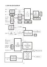
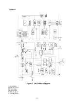
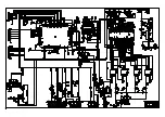
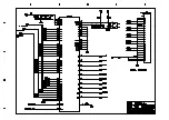
For the working principle of LC-22K9 please refer to LC-22K9 block diagram of the complete TV set.
Following is a short description of the signal flow:
RF signal through an integral tuner TUNER201 produces complete color TV signal which is input,
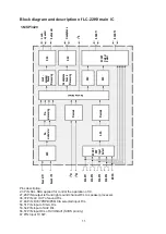
together with AV1/SVHS(SVHS in priority)AV2 and PCMCIA video signals, into U29 VPC3230D for
conversion selection and decoding. Except for being decoded the selected video signal is divided in two
routes: one is fed to AV output terminal and another route of signal to special 21 line decoder U32
Z86229 of CCD/V-CHIP for decoding. After decoding by U32, the signal is sent back to U29 with
R,G,B,FB format and superimposed to the original picture decoded, then sent to U13 FLI2310 in
ITU-R656 of 8B1T format for progressive line processing.
YPbPr signal, after analog to digital conversion by U30 MST9883 into YUV with 24BIT is also sent
to FLI2310.
Above two routes of signal are processed by FLI2310 for matrix, color density and tint and then
output as RGB with 24 BIT into the main processor chip U12 JAG-ASM. There are other two routes of
signals: one route is RGB signal of VGA for computer, another route is DV1 into RGB signal with 24 bit to
U12 through interface of U15 TFP403/501. Three routes of signal are processed in U12 for picture
format. Among them, one route of VGA after A/D conversion for RGB is subject to selection for
conversion, together with other two routes, and then processed for digital display including OSD AND
GAMMA correction, and brightness and contrast processing and changed into 1024*768 format. The
RGB signal with 24BIT is output to the LVDS converter, U31 DS90C383A, for conversion into the
signal format which the screen can accept, that is, three pairs of low voltage differential signal and one
pair of time signal. And they are further sent to LCD screen for picture display. The PWM of U12 is also
used to control the brightness of the background light.
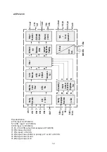
The second sound IF signal SIF output from tuner is sent to sound frequency processor N201
MSP3420; the sound frequency signal of YPRPB,DVI and PCMCIA is also sent to N201 after switching
over and selection by switch U34 HEF4052. The AV1/SVHS,AV2 and VGA audio signal are also sent to
N201 respectively, where the second sound IF SIF is first demodulated to the audio signal which,
together with four way audio signal, is selected for conversion, and then further sound magnitude
controlled and sound effect treated. The output of left and right signal R/L is divided into two routes: one
is sent to SRS sound field processor N203 M62494 for SRS surrounding sound processing, and further
used to drive the speaker after the D-type sound power amplification N207 LX1722 and
amplification of N205,N206,N208,N210 SI4532DY; the other route is used to drive earphone after
power amplification N212 TLE2142.
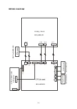
Power is supplied from power adapter and then converted into the power required by various
channels and circuits.
Summary of Contents for LC22K9
Page 1: ...COLOR TELEVISION LC22K9 ...
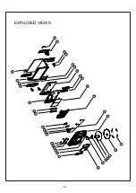
Page 23: ...EXPLODED VIEWS 21 ...
Page 25: ......
Page 26: ......
Page 27: ......
Page 28: ......
Page 29: ......
Page 30: ......
Page 31: ......
Page 32: ......
Page 33: ......
Page 34: ......
Page 35: ......
Page 36: ......
Page 37: ......
Page 38: ......
Page 39: ......
Page 40: ......
Page 41: ......
Page 42: ......
Page 43: ......


