


3
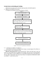
Instructions on adjusting and testing
PM5518(Video signal generator),K-7253(VGA signal generator),CA210(White balancer
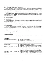
2.1. Adjustment and calibration flow process
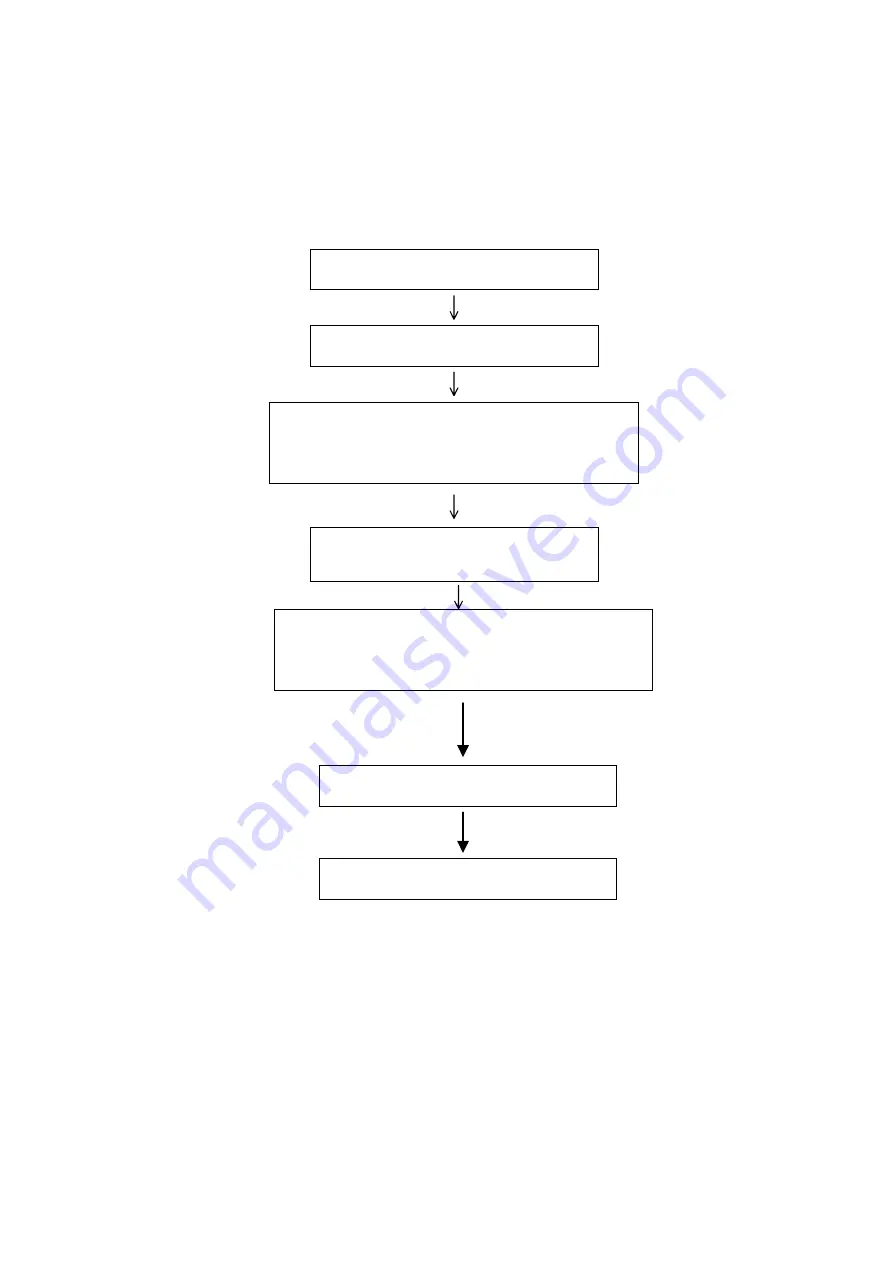
For adjustment and calibration flow process diagram, see figure 1
Figure 1
2.2 Adjustment and calibration of complete set
Connect different CPU board and analog board according to connection diagram 203-L27K60-01JL.
Put power supply on, see if the display is normal.
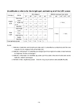
Method to enter factory menu:
Continuously push “VOL+” “Mute” and “Video” keys to enter the
factory menu; select different items of adjustment and calibration, when the first line of each adjustment
item is in high brightness; push the “ENTER” key to select different adjustment item; push “ENTER” key
after the mode is selected with VGA input and select three color temperatures 6500K,9300K,12000K;
push “MENU” to quit the factory menu.
Check CPU and analog board
Combined test for general assembly
Preset before outgoing from factory
Connect to central signal source, check if various TV functions
(station skipping, modulate quantity control etc), check if the
output of earphone and speaker are normal
Input AV/S, HDTV signal and check various
functions under terminals
Input VGA signal (one format) and check if display is
normal in the state of PC and various functions (analog
quantity control, line/field center etc.)
Check accessories and then packing
Figure 1 Flow process of Adjustment and calibration
Summary of Contents for LC27K6
Page 1: ...COLOR TELEVISION LC27K6 ...
Page 13: ...11 3 JAG ASM ...
Page 15: ...13 ...
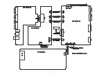
Page 18: ...EXPLODED VIEW 16 ...
Page 53: ......
Page 54: ......
Page 55: ......
Page 56: ......
Page 57: ......
Page 58: ......
Page 59: ......
Page 60: ......
Page 61: ......
Page 62: ......
Page 63: ......
Page 64: ......
Page 65: ......
Page 66: ......
Page 67: ......
Page 68: ......
Page 69: ......
Page 70: ......
Page 71: ......
Page 72: ......
Page 73: ......


