23
then replace Y BUFFER (upper, lower) in respect to the upper, lower part of the dark line on the screen.
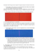
3. There appear on the screen one or several horizontal lines that are much brighter
than the remaining horizontal lines at the edge:
Check if the socket between Y driving board and Y BUFFER is plugged well. If not, plug it well. If yes
then replace Y BUFFER (upper, lower) in respect to the upper , lower part of the dark line on the screen.
4. There appear on the screen one vertical unlit line or a vertical entirely unlit block
a. If it’s one vertical unlit line, then COF has problem.
b. If it’s a vertical entirely unlit block, then first check if the connection socket between COF and logic
BUFFER has problem. If not, check if the connection socket between the logic BUFFER and the logic
board is normal. If yes, replace the logic BUFFER. Finally, if the problem still remains when the
replacement is over, then replace the logic board.
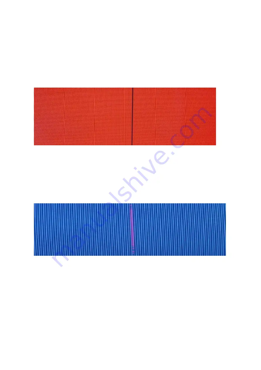
5. There appears on the screen a mono color signal and one or several vertical bright
lines of other colors:
a. If it’s a vertical bright line of other colors, then the problem lies with COF or the screen.
b. If it’s an entire vertical block of other colors, then first check to see if the connection socket
between COF and logic BUFFER has problem. If no problem, check if the connection
socket between the logic BUFFER and the logic board is normal. If it’s normal, then replace
the logic BUFFER. If the problem still remains after the replacement, then replace the logic
board. Finally if the problem is still there, then the problem lies with COF.
6. There appear on the screen abnormal bright spots or blocks that are different from
what’s described above:
a. Check if the connection socket between COF and logic BUFFER board has been well plugged.
b. Replace the logic BUFFER board. If it’s not solved then replace logic board. If the problem still
remains, then it’s the problem with COF.
Summary of Contents for PH-42R6
Page 1: ...PDP TELEVISION PH 42R6 Canada...
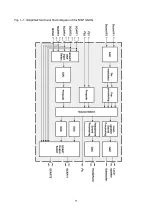
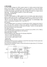
Page 11: ...9 Fig 1 1 Simplified functional block diagram of the MSP 34x0G...
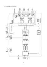
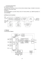
Page 13: ...11 INTERNAL BLOCK DIAGRAM...
Page 26: ...Power board...
Page 27: ...Power board power board...
Page 39: ...APPENDIX Exploded view PH 42X6...
Page 42: ...603 PH42R60 10 Ver 1 0...


