background image

PDP

 TELEVISION

PH-50HA31

Summary of Contents for PH-50HA31

Page 1: ...PDP TELEVISION PH 50HA31...

Page 2: ...nstructions Method of software upgrading Working principle analysis of the unit Block diagram IC block diagram Wiring diagram Troubleshooting guide Schematic diagram APPENDIX A Assembly list APPENDIX...

Page 3: ...n the vicinity of water bath room laundry water chute of kitchen sources of fire heat radiation parts or direct exposure to sunlight Otherwise there will be kickbacks 1 5 In case foreign substances su...

Page 4: ...erature Scope for operation 0 50centigrade Scope for storage 15 60centigrade Humidity Scope for operation 20 80 Scope for storage 20 80 1 15 If a fixed picture is displayed for a long time difference...

Page 5: ...color temperature etc Please handle it carefully Alignment instructions 1 Test equipment PM5515 video signal generator MK8258 YUV VGA signal generator CA210 white balancer 2 The alignment flow chart s...

Page 6: ...ent page of factory menu AUTO COLOR enter TEST PATTERN and use OK button to select SMPTE COLOR BAR then enter START and press OK SMPTE COLOR BAR signal of MK8258 should be OIRE standard that s ATTER 9...

Page 7: ...363 60 004 65 VESA 12 1024 X 768 56 476 70 069 75 VESA 13 1024 X 768 60 023 75 029 78 75 VESA 4 6 YPBPR and TV brightness check use 100IRE white window signal 5 Ex factory setting of user menu 1 Sele...

Page 8: ...switch the power on Check to see if the power plug has been inserted properly into the socket No picture and sound Check to see if the power supply of liquid crystal TV has been switched on as can be...

Page 9: ...heck the distance or angle from the monitor Check if there is any obstruct between the remote control and the TV set Check if the remote control signal receiving window is exposed to strong fluorescen...

Page 10: ...5 D0002 645 2 Open iDev exe 3 Click enter the setting interface Set Serial Port to the current COM port set the Baud Rate to 1152000 Image Path to the path of the new software If the new software rene...

Page 11: ...software begins to be written 6 After the software written Press the power key local keypad and holding for several second to force power off TV set 7 Turn on the TV again and enter the factory menu...

Page 12: ...nformation source decoding in the format of standard serial TS stream HD video signal via decoding to A D conversion and OSD superposition at last send to LVDS drive level for PDP panel HD audio signa...

Page 13: ...R1 PW2300 R2S15102 AV1 AV2 YPBPR2 RS232 AV Audio Out S Video PLC915 IR KEY AV Out MAX3232C CAT99 83 ATSC DIF ATSC DIF NTSC CVBS Y C I2C I2C LVDS M52797SP CS5340 CS4345 R2S15903 I2S I2S HDMI1 FSHDMI04...

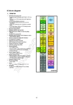
Page 14: ...12 IC block diagram 1 ZR39760...

Page 15: ...Pixel Clock Synthesizer The triple ADC support 12 110 MHz Sampling Rate It integrated 5 bit pixel clock phase adjustment for precise sample timing control Its Output support 4 2 2 Format Mode and it...

Page 16: ...14...

Page 17: ...External Clamp Input 30 Horizontal SYNC Input 31 Vertical SYNC Input 29 Hold PLL Frequency do not track HSYNC 56 Serial Interface clock 57 Serial Interface data pin 55 Serial interface address pin 70...

Page 18: ...5 28 32 36 40 41 44 47 50 53 60 61 63 68 80 Ground 3 R2S15903SP R2S15903SP is an audio signal processor It has MUTE and Volume Tone control It can support 5 input selector Pin descriptions of R2S15903...

Page 19: ...plifier The output power can reach 20W 10 THD N with 8 speakers 18V power supply eliminating the need for heat sinks Pin description 1 audio out left audio output 15 audio out right audio output 11 au...

Page 20: ...itch with I2C bus control Pin description 1 VCC 9V 17 VIDEO OUT 2 4 AV2 L R IN 19 21 L R OUT 2 AV2 VIDEO IN 20 AV CVBS OUT 6 TV CVBS IN 23 TUNER_IN 5 7 Y Pr Pb1 L R IN 22 24 TV L R IN 8 10 Y Pr Pb2 L...

Page 21: ...2 Y P B P R 1 2 XB01 VIDEO IN XB7 S X109 XB3 XB1 XB2 XV1 X509 X508 X505 X506 X501 220V Backlight power Power board Logic board Household Power Speaker Tuner Main board Port Port Port Port Earphone Ter...

Page 22: ...e abnormal in all channels Begin Turn on the TV Check if XP1 9 on the main board is 3 3V if it s 0V check the power supply of the power board A green indicator lights Check if the pin3 of XP1 on the m...

Page 23: ...ck the power board No sound No picture Power board problem Refer to 3 checking procedure Refer to 4 checking procedure No Yes Check the power board With picture but no sound Check if the voltage of so...

Page 24: ...ral circuit Refer to 6 7 8 9 10 11 12 checking procedure Check if CB106 and CB49 input signals AV IN Check if LB7 LB8 input signals S Video Yes No Yes No Check if pin20 of NB8 outputs signals Check N1...

Page 25: ...TSC channel please check N228 emphatically Check if pin4 of TUN1 output signals Yes No Yes Check if CB154 outputs signals Check TUN1 power supply and the peripheral circuit Check N100 and its peripher...

Page 26: ...DC of N503 pin12 Check N503 or peripheral circuit Supplementary power supply N502 has problem N N N Y Y Y No DC voltage output Check if DC voltage of C550 is 3 3V 5V Check if DC voltage of V505 B is...

Page 27: ...602 L37HA37 01 11...

Page 28: ...602 32HA37 01 602 32HA37 01 602 32HA37 01 602 L37HA37 01 11...

Page 29: ...602 L37HA37 01 11...

Page 30: ...602 L37HA37 01 11...

Page 31: ...602 L37HA37 01...

Page 32: ...602 L37HA37 01 11...

Page 33: ...602 L37HA37 01 11...

Page 34: ...602 L37HA37 01 11...

Page 35: ...602 L37HA37 01...

Page 36: ...602 L37HA37 01 11...

Page 37: ......

Page 38: ......

Page 39: ...71590301 M52797 5275279701 MST9983 5279983003 FSHDMI04 5270004002 Key board 6HU0670510 IR board 6HA0150910 Interface connection board 6HA0082910 Power filter board 6FK0105110 Power board 6HA0182010 Re...

Page 40: ...APPENDIX EXPLODED VIEW PH50X31...

Page 41: ...PU board 11 power switch bracket 12 key board 13 wall mounting bracket 14 back cabinet 15 back baffle 16 speaker back cover left 17 speaker back cover right 18 stand 19 speaker 20 IR board 21 power co...

Page 42: ...9350HA3110 Ver 1 0...

Reviews: