4
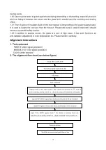
Fig-1 adjustment flow-chart
3. Description of adjustment
3.1 Unit adjustment
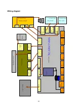
Connect the signal processing board, side AV board, button board and remote control receiver
board according to the wiring diagram. Connect with power and observe the display.
Method for using factory menu:
press ”INPUT” button, then press”2580” to enter level one factory
menu. Press ”CH+” and “CH-“ to select adjustment page, then press “OK” to access. Press “CH+”
and “CH-“ to move cursor up and down, when the cursor stays on a certain adjustment item, press
“VOL-“ and “VOL+” to adjust. Press “MENU” exit to the level one factory menu; press “EXIT” to exit
from the factory menu at any situation.
Note: channel switch isn’t available at adjustment menu, only after return to level one factory menu,
you can switch channel.
3.2 Auto color adjustment
3.2.1 input 16 level gray-scale signal from MK8258 to D-sub channel, enter auto color adjustment
page of factory menu (AUTO COLOR), enter TEST PATTERN and use OK button to select GREY
SCALER16, then enter START and press OK.
3.2.2 input SMPTE COLOR BAR signal from MK8258 to YPbPr channel, enter auto color
adjustment page of factory menu (AUTO COLOR), enter TEST PATTERN and use OK button to
select SMPTE COLOR BAR, then enter START and press OK. (SMPTE COLOR BAR signal of
MK8258 should be OIRE standard, that’s ATTER 96. TYPE CODE of PATTEREDID 6.)
Note: after auto color adjustment, it must press the power button on the remote controller to turn off
the unit and then turn on, can the information be stored in FLASH!
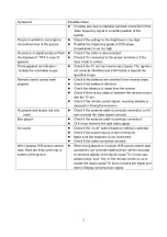
4 Performance check
4.1 TV function
Connect RF-TV terminal to the central signal source, enter the setup menu
→
auto search, check if
there is station skipping, the output of earphone and speaker, the picture are normal. The signal
should include NTSC and ATSC.
4.2 AV/S-VIDEO terminal
Input AV/S signal, check if the picture and sound are normal.
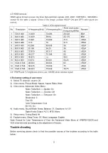
4.3 YPbPr/YCbCr terminal
Input YUV signal (VG-849 signal generator), separate input YUV format signal of table 1 and check
if the picture and sound are normal.
Table 1 YUV signal format
No
H-frequency (KHz)
V-frequency (KHz)
Signal
1 15.734
59.94
SDTV
480i
2 31.469
59.94
HDTV
480p
3 44.955
59.94
HDTV
720p
4 33.716
59.94
HDTV
1080i
4.4 VGA terminal
Input VGA signal (VG-849 signal generator), separate input VGA format signal of table 2 and check
if the picture and sound are normal. If the image is deflection of the H-field, select manual correction
of Advanced Video Menu.
Summary of Contents for PH-50HA31
Page 1: ...PDP TELEVISION PH 50HA31...
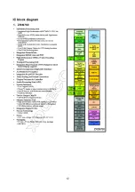
Page 14: ...12 IC block diagram 1 ZR39760...
Page 16: ...14...
Page 27: ...602 L37HA37 01 11...
Page 28: ...602 32HA37 01 602 32HA37 01 602 32HA37 01 602 L37HA37 01 11...
Page 29: ...602 L37HA37 01 11...
Page 30: ...602 L37HA37 01 11...
Page 31: ...602 L37HA37 01...
Page 32: ...602 L37HA37 01 11...
Page 33: ...602 L37HA37 01 11...
Page 34: ...602 L37HA37 01 11...
Page 35: ...602 L37HA37 01...
Page 36: ...602 L37HA37 01 11...
Page 37: ......
Page 38: ......
Page 40: ...APPENDIX EXPLODED VIEW PH50X31...
Page 42: ...9350HA3110 Ver 1 0...


