background image

PDP

  TELEVISION

PH-50HU31

Summary of Contents for PH-50HU31

Page 1: ...PDP TELEVISION PH 50HU31...

Page 2: ...nstructions Method of software upgrading Working principle analysis of the unit Block diagram IC block diagram Wiring diagram Troubleshooting guide Schematic diagram APPENDIX A Assembly list APPENDIX...

Page 3: ...n the vicinity of water bath room laundry water chute of kitchen sources of fire heat radiation parts or direct exposure to sunlight Otherwise there will be kickbacks 1 5 In case foreign substances su...

Page 4: ...erature Scope for operation 0 50centigrade Scope for storage 15 60centigrade Humidity Scope for operation 20 80 Scope for storage 20 80 1 15 If a fixed picture is displayed for a long time difference...

Page 5: ...signal generator VG 849 VGA and HDMI signal generator CA210 white balancer 2 Alignment flow chart The alignment flow chart is shown as fig 1 Fig 1 adjustment flow chart 3 Unit adjustments Connect all...

Page 6: ...st LZ100 to value 2 5V of TP5 B face then wed J2 3 2 2 IF AGC adjustment Input 184 25MHz RF signal of 60DBuv from RF terminal for china and 175 25MHz for America adjust RZ133 to value 2V of TP1 B face...

Page 7: ...l if there are channels be skipped Check CCD and V CHIP function for America 4 2 AV S YPbPr terminals Input AV S YPbPr YCbCr HD signal check if it is normal 4 3 VGA terminal Insert VGA terminal input...

Page 8: ...15 pins the serial cable connects the PC and the upgrade instrument the VGA cable connects the TV and the upgrade instrument 2 The steps for upgrading software 1 Please confirm that the connection wi...

Page 9: ...ction wires and check if ISP item of the factory menu is set to 1 if not please set it to 1 4 After connection is done it needs to read the Binary document Press Read as shown below 5 Search the docum...

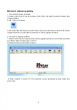
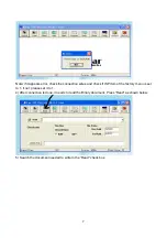
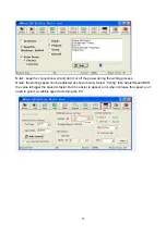
Page 10: ...8 6 Select the document then the window will appear as shown below Select...

Page 11: ...9 7 Press Auto to select the writing function Select the items shown in the picture above a Read File...

Page 12: ...e Device e File Area 8 Press Run to begin the writing program wait till the blue bar is complete After writing it will display OK If there is error appeared shown as below press Run again to rewrite t...

Page 13: ...writing process Note2 the writing speed can be adjusted as shown below Select Config then adjust Speed BAR the value is bigger the speed is faster But it is easier to appear error when increase the sp...

Page 14: ...witch NW200 HEF4052BT selection to MST9U88L AV1 and S VIDEO share one audio port Video and audio signal of VGA HDMI will be sent to MST9U88L too The main IC NS4 MST9U88L is a high performance and full...

Page 15: ...YPbPr2 L R AV1 L R AV2 L R TUNER TV V TV SIF CVBS V AV OUT IIS L R AV OUT LCD TV CONTROLLER MST9X88LD AUDIO SW HEF4052 HP AMP BH3547F AUDIO AMP MP7722 HEAD PHONE EDID 24C02 EEPROM FLASH DDR PANEL SPEA...

Page 16: ...video and audio decoder a video de interlacer a scaling engine the MStarACE 3 color engine an on screen display controller an 8 bit MCU and a built in output panel interface With external frame buffe...

Page 17: ...74 AV1 S AV2 YpbPr1 YpbPr2 L R input 178 search program synchronous test input 188 HDMI hot plug test output 189 image switch output 192 backlight control output 193 panel voltage contort output 85 86...

Page 18: ...16...

Page 19: ...ating the following 180m power MOSFETs Startup Shutdown pop elimination Short circuit protection Mute Standby The MP7722 utilizes a single ended output structure capable of delivering 2 x 20W into 4 s...

Page 20: ...18...

Page 21: ...19 Pin description 1 7 L R input 19 14 L R output 6 10 mute control input...

Page 22: ......

Page 23: ...nd if interfered possibly by the equipment like transmitting antenna non professional radio station and cellular phone 1 2 TV set Symptoms Possible cause Unable to switch the power on z Check to see i...

Page 24: ...teries are installed in the reverse order z Check if the battery is effective z Check the distance or angle from the monitor z Check if there is any obstruct between the remote control and the TV set...

Page 25: ...upply board Press POWER button on the unit or remote sensor control and check the indicator Check if the PIN27 of X304 on 01 board is high level Check if the PIN11 of X303 in main board is high level...

Page 26: ...off the TV turn on again display picture Adjust main board again Which is no signal of channels Replace main board Check if 1VPP signal and noise wave of XB201 11 on the TV board Check if output IF si...

Page 27: ...PIN2 8 13 and 18 voltage of NA6 is normal Check power board Check PIN3 and PIN7 output wave of NA6 Check PIN10 wave of NZ100 Check PIN11 wave of TUNER1 Replace TUNER1 Replace NA6 Replace NS4 Replace...

Page 28: ...main board...

Page 29: ...main board...

Page 30: ...main board...

Page 31: ...main board...

Page 32: ...analog board...

Page 33: ...key board...

Page 34: ...IR board...

Page 35: ...AV board...

Page 36: ...Power board A...

Page 37: ...Power board B...

Page 38: ...6HU05901B0 NS4 MST9U88L 5270988001 Interface connection board 6HU0544610 Key board 6HU0670510 IR board 6HU0670910 Power filter board 6FK0105110 Power board 6HV0082010 Remote control 6010Y04600 Panel...

Page 39: ...APPENDIX A EXPLODED VIEW PH50x31...

Page 40: ...ard 11 power switch bracket 12 key board 13 wall mounting bracket 14 back cabinet 15 back baffle 16 speaker back cover left 17 speaker back cover right 18 stand 19 speaker 20 IR board 21 power cord 22...

Page 41: ...9350HU3123 Ver 1 0...

Reviews: