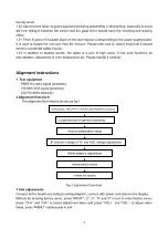

1
Safety precautions
Please read the “Points for attention for the Maintenance & Repair of PDP” and “Criterion for
Identifying the Defects on Screen” as below, before inspecting and adjusting the TV set.
1. “Points for attention for the Maintenance & Repair of PDP”
To avoid possible danger, damage or jeopardy to health and to prevent PDP screen from new
damage, the maintenance people must read the following carefully. If they ignore the following
warnings, there will be deathful risks:
1.1 Screens vary from one model to another and therefore not interchangeable. Be sure to use the
same type of screen in the replacement.
1.2 The operation voltage is approximately 350v for PDP module (including screen, driving circuit,
logic circuit and power module). If you want to conduct maintenance work on PDP module when the
set is in normal operation or just after the power is off, you must take proper measures to avoid
electric shock and never have direct contact or touch with the circuitry of the working module or
metal parts. That’s because within a short time relatively high voltage still remains on the capacitor
of the driving part even after the power is off. Make sure to begin relevant maintenance operation at
least one minute after the power is off.
1.3 Don’t apply on the module any power supply that is higher than the specification. If the power
supply used deviates from the value given in the specification, there might be a possibility of leading
to fire or damage to the module.
1.4 Never have operation or mounting work under unsuitable environment such as areas in the
vicinity of water (bath room, laundry, water chute of kitchen), sources of fire, heat-radiation parts or
direct exposure to sunlight. Otherwise there will be kickbacks.
1.5 In case foreign substances such as water, liquid, metal slices or others fall into the module
carelessly power must be cut off immediately. Keep the module as it is and do not move anything on
the module. Otherwise it might be possible to contact the high voltage or cause shock short circuit
so that it may lead to fire or electric shock.
1.6 If there is smoke, abnormal smell or sound from the module, please cut the power off
immediately. Likewise in case the screen doesn’t work when the power is on or during the
operation, please also cut off the power at once. No more operation in this case.
1.7 Do not remove or plug its connection wire when the module is in operation or right after the
power is off. That’s because there remains a relatively high voltage on the capacitor of the
driving circuit. If there is a need to remove or plug in the connection wire, please wait at
least one minute after the power is off.
1.8 Considering the module has a glass faceplate, please avoid extrusion by external force lest
it should cause glass breakage that may get people injured. Two people are needed in
cooperation to move this module lest contingency takes place.
1.9 The complete TV set is designed on the basis of full consideration of thermal dissipation by
convection, with the round hole on the top for heat emission. To avoid overheat, please do
not have any covering on the hole during normal operation and never put it in the place
Attention:
This
service manual is only for service personnel to take reference with. Before
servicing please read the following points carefully.
Summary of Contents for PH-50HU31S
Page 1: ...PDP TELEVISION PH 50HU31S...
Page 12: ...10...
Page 14: ...12...
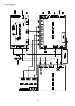
Page 15: ...IF adjust Wiring diagram 13...
Page 19: ...page 1 of 4...
Page 20: ...page 2 of 4...
Page 21: ...page 3of 4...
Page 22: ...page 4 of 4...
Page 23: ...interface connector...
Page 24: ...KEY board...
Page 25: ...IR receiver board...
Page 26: ...TV board...
Page 27: ......
Page 28: ......
Page 30: ...APPENDIX EXPLODED VIEW PH50X31...
Page 32: ...9350HU3111 Ver 1 0...


