2
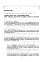
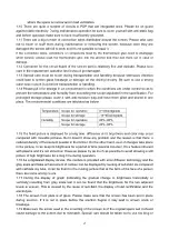
where the space is narrow and in bad ventilation.
1.10 There are quite a number of circuits in PDP that are integrated ones. Please be on guard
against static electricity. During maintenance operation be sure to cover yourself with anti-static bag
and before operation make sure to have it sufficiently grounded.
1.11 There are a big number of connection wires distributed around the screen. Please take care
not to touch or scuff them during maintenance or removing the screen, because once they are
damaged the screen will fail to work and it’s not possible to repair it.
If the connection wires, connectors or components fixed by the thermotropic glue need to disengage
when service, please soak the thermotropic glue into the alcohol and then pull them out in case of
damage.
1.12 Connector for the circuit board of the screen part is relatively fine and delicate. Please take
care in the replacement operation lest it should get damaged.
1.13 Special care must be taken during transportation and handling because strenuous vibration
could lead to screen glass breakage or damage on the driving circuitry. Be sure to use a strong
outer case to pack it up before transportation or handling.
1.14 Please put it for storage in an environment in which the conditions are under control so as to
prevent the temperature and humidity from exceeding the scope stipulated in the specification. For
prolonged storage please cover it with anti-moisture bag and have them piled and stored in one
place. The environmental conditions are tabulated as below:
Temperature Scope
for
operation 0~50centigrade
Scope for storage
-15~60centigrade
Humidity
Scope for operation
20%~80%
Scope for storage
20%~80%
1.15 If a fixed picture is displayed for a long time, difference in its brightness and color may occur
compared with movable pictures. But it doesn’t show any problem and the reason is that there is
reduced density of fluorescent powder in the former. On the other hand, even if changes take place
in the picture, it can keep its brightness for a period of time (several minutes). It’s a feature inherent
with plasma and it’s not abnormal. However please try as much as possible to avoid showing a still
picture of high brightness for a long time during operation.
1.16 As a digitalized display devise, this module is provided with error diffusion technology and the
gray scale and false enhancement of contour can be displayed by reusing of sub-field. As compared
with cathode ray tube, it can be found in the moving picture that at the brim of the face of a person
there are some wrong colors.
1.17 During the display of graph (indicating the gradual change in brightness horizontally or
vertically) resulting from gray scale test it can be found that the brightness for the two adjacent
levels is uneven. This is caused by the reuse of sub-field, the display of load rectification and the
electrolysis.
1.18 The screen front plate is of glass. Please make sure that the screen has been put in place
during erection. If it is not in place before the erection begins it may lead to screen crack or
breakage.
1.19 Make sure the screw used in the mounting of the screen is of the original specs lest it should
cause damage to the screen due to mismatch. Special care should be taken not to use too long or
Summary of Contents for PH-50HU31S
Page 1: ...PDP TELEVISION PH 50HU31S...
Page 12: ...10...
Page 14: ...12...
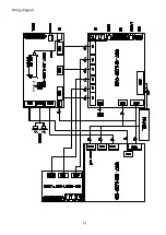
Page 15: ...IF adjust Wiring diagram 13...
Page 19: ...page 1 of 4...
Page 20: ...page 2 of 4...
Page 21: ...page 3of 4...
Page 22: ...page 4 of 4...
Page 23: ...interface connector...
Page 24: ...KEY board...
Page 25: ...IR receiver board...
Page 26: ...TV board...
Page 27: ......
Page 28: ......
Page 30: ...APPENDIX EXPLODED VIEW PH50X31...
Page 32: ...9350HU3111 Ver 1 0...


