background image


1 safety instruction 

1.1 X-RAY radiation precaution 
1.1.1 Excessive voltage will cause harmful X-ray. To avoid this radiation hazard, the high voltage should 
fall within the limitation. The appliance works at AC 120V, 60Hz. The high voltage of zero beam current 
should be within 29.0kV on condition that the main power (B+) voltage is AC135V. And it should not 
exceed 30kV in any condition.   
* Keep the main power voltage at 135V when checking the high voltage. 
1.1.2 The primary source of X-RAY RADIATION is the CRT. The CRT of this TV set have gotten the 
approval of safety authentication inspection. The replacement CRT should be exactly the same type and 
specification CRT which has gotten a similar safety approval, and check the high voltage according to 
the HIGH VOLTAGE CHECK procedure. 
1.2 safety precaution 
a. Since the power supply circuit of this receiver is directly connected to the AC power line, an isolation 
transformer is necessary during dynamic service to avoid possible shock hazard. 
b. Always discharge the graphite layer conductor when moving the CRT. 
c. Disconnect the power cord before replacing parts. 
d. When replacing high-power resistor, keep the resistor 10 mm away from the circuit board. 
1.3 Component safety precaution 
Many electrical and mechanical parts in the chassis have special safety-related characteristics. These 
characteristics are often passed unnoticed by a visual inspection. Replacement parts which have these 
special safety characteristics are identified in this manual and its supplement electrical components 
having such features are shaded or marked by        on the schematic diagram and the parts list. Before 
replacing any of these components, read the parts list in this manual carefully. The use of substitute 
replacement parts which do not have the same characteristic as specified in the parts list may create 
shock, fire, X-RAY RADIATION or other hazards. 

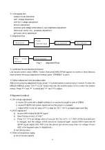
2.General instruction 

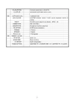
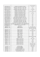
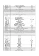
2.1 Copy the standard model data to let EEPROM of the chassis have those data before placing it on the 
unit, do “factory adjustment” if necessary. If use a blank EEPROM directly, you should preset IIC data 
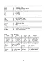
and then do other common adjustment. Refer to TABLE1 to preset EEPROM. 
2.2 the adjustment should be done under following circumstances without additional instruction 
a) Alternating current 120V/60Hz 
b) Preheat at least 30 min 
2.3The unit has auto degaussing circuit, the auto degaussing process can be finished within 1s when the 
main power. only when turn on the unit at least 30min after last time turn off TV does the auto 
degaussing circuit work.   
2.4 If the CRT with magnetism affects color purity and convergence, when the auto degaussing 
eraser. if the color purity and convergence are still not very good, then corresponding adjustment 
should be done. Refer to picture tube adjustment method for adjustment. 

3

 Alignment instruction


Note: This service manual is only for professional service personnel’s reference. Before

servicing the unit, please read the following items carefully. 

Summary of Contents for TK2416

Page 1: ...COLOR TELEVISION TK2426 TK2416...

Page 2: ...CONTENTS Safety instruction 1 General instruction 1 Alignment instruction 2 Alignment flow 2 Alignment method 3 BLOCK DIAGRAM 8 MAIN IC 9 Parts list 13 Exploded view 31 Schematic diagram 33...

Page 3: ...pection Replacement parts which have these special safety characteristics are identified in this manual and its supplement electrical components having such features are shaded or marked by on the sch...

Page 4: ...and P to select and V and V to adjust 4 Alignment method 4 1 B voltage adjustment a connect B point with a digital voltmeter to measure the negative pole of VD524 b receive PHILIPS test pattern signal...

Page 5: ...000 K 8MPCD X 0 270 0 008 Y 0 283 0 008 a receive full white signal b select factory menu3 c on the basis of blue adjustment RD GD of M3 let to white balance coincide with standard 4 8 Filed scanning...

Page 6: ...the magnetic eraser If the effect is still not very good you can adjust color purity and convergence 4 13 Color purity correction a Turn on your TV b At least 15 minutes later use anti magnetized coi...

Page 7: ...ce push the rubber wedge into space between picture tube and deflection yoke to fixate the deflection yoke temporarily e Place the rubber wedge whose overlay paper has been removed at the bottom space...

Page 8: ...P BTSC ST 13 BTSC SP 12 BTSC L1 1 BTSC A1 15 BTSC A2 0 BTSC TC 0 BTSC STS 0 BTSC ADJ MI Items Variable Preset M5 MODE STANADARD standard soft floweriness BRIGHT 75 CONTRAST 75 COLOR 50 SCBRIGHT 20 YDE...

Page 9: ...tude control of inside FMATT 45 UOC sound output of amplitude BTSC 38 COMBFILTRE 0 N comb filter HEADPHONE 0 earphone function selection VM OPTION 0 VM function selection FRANCE 1 French SPANISH 1 Spa...

Page 10: ...B OUT V OUT H OUT S TRAP Vo V2i V1i Y Cr Cb ARi2 ARi1 ALi2 ALi1 S VHS 24C08 POWER UNIT 135V 24V 16V 8V 5V 3 3V CRT PCB V IN TDA8177 V OUT H IN H OUT H OUT DY 200V 15V 15V SCREEN FOCUS TDA8377 Vi1 OUT1...

Page 11: ...BY mode high level Power OFF For Power ON this pin will be reduced to low SCL 2 I2 C bus clock line SDA 3 I2 C bus data line TUNING 4 tuning Voltage Vt PWM output P3 0 NTSC SW 5 Port 3 0 or NTSC outpu...

Page 12: ...current input VSC 26 Vertical sawtooth capacitor TUNER AGC 27 Tuner AGC output AUDEEM SIFIN1 1 28 Audio deemphasis or SIF input DECSDEM SIFIN2 29 decoupling sound demodulator or SIF input 2 GND2 30 g...

Page 13: ...RESET 60 reset VDDP 61 digital supply to periphery 3 3 V P1 0 INT1 62 TV AV AV1 AV2 S VHS mode Output P1 1 T0 63 TV AV AV1 AV2 S VHS mode Output P1 2 INT0 64 Remote control signal input AN7522 Functi...

Page 14: ...4 1 5 3 6 2 3 2 6 2 6 2 6 PIN 49 50 51 52 53 54 55 56 57 58 59 60 61 62 63 64 V 2 3 7 2 2 7 2 7 2 7 3 5 0 3 5 0 1 1 7 1 8 0 3 5 0 1 0 1 5 TDA8177 PIN 1 2 3 4 5 6 7 V 0 7 15 12 15 0 3 15 9 0 07 AN 752...

Page 15: ...851 24014 14 SCREW SJ2824 ST4X14C Y 851 24020 14 SCREW SJ2824 ST4X20C Y 851 24020 14 SCREW SJ2824 ST4X20C Y 851 53010 31 SCREW SJ2825 ST3X10FT D Zn 851 53012 11 SCREW SJ2825 ST3X12C D Zn 851 53014 31...

Page 16: ...CONTROL UNIT ZZ010 BXATB017F K TUNER ET 5T5E AF108 A101 CAF104K1 H FC POLYESTER CAPACITOR 50V 0 1u C326 C338 C365 C411 C431 C511 CAF223J1 H FC POLYESTER CAPACITOR 50V 0 022u C05 CAF224K1 H FC POLYESTE...

Page 17: ...STER CAPACITOR CBB12 400V 0 039u C457 CPFX6R8MY01NP ELECTROLYTIC CAPACITOR 50V 6 8u NONPOLARIZED C446 DH24R5M001 NC THERMISTOR PTC 4 5ohm 3 END PS501 DN15R0M001 NH NTC 5ohm R502 DRBAV21 NJ DIODE BAV21...

Page 18: ...10V 9ohm 25 M90X0003 91 INSULATING CUSHION 18 13 D4 8 Z1 MB0X0011 G8 FUSE SOCKET FUSE HOLDER F501A F501B MB1X0040 BF 12V RADIATOR H N505 MB1X0114 BF 5V RADIATOR CUBA H N503 MB1X0163 BG PINCUSHION CORR...

Page 19: ...OR 1W 1K R466 RSE1R5J5DCCND METAL RESISTOR 1W 1 5 R406 RSE1R8J5DCCND METAL RESISTOR 1W 1 8 R408 RSE220J5ACCND METAL RESISTOR 1W 22 R300A RSF101J5ACDND METAL RESISTOR 2W 100 R407 RSF103J5ACDND METAL RE...

Page 20: ...STOR 1 4W 1 8K G R403 467 2D218 G0 METAL RESISTOR 1 4W 1 8K G R405 471 2001K 00 PEAKING COIL SPT0305 1R0K 5 L302 666 12301 00 FERRITE BEAD TY23X13 5X6 666 12301 00 FERRITE BEAD TY23X13 5X6 681 40003 0...

Page 21: ...1 459 2210K 002 CERAMIC CAPACITOR CK45 B1H102KYR C401 459 2210K 002 CERAMIC CAPACITOR CK45 B1H102KYR C402 459 2210K 002 CERAMIC CAPACITOR CK45 B1H102KYR C721 459 2210K 002 CERAMIC CAPACITOR CK45 B1H10...

Page 22: ...ROLYTIC CAPACITOR CD110 16V 47uF M C811 464 6D647 M02 ELECTROLYTIC CAPACITOR CD110 16V 47uF M C823 464 6D647 M02 ELECTROLYTIC CAPACITOR CD110 16V 47uF M C121 464 6D647 M02 ELECTROLYTIC CAPACITOR CD110...

Page 23: ...67 1C110 H03 CARBON RESISTOR 1 6W 100 J R401 467 1C110 H03 CARBON RESISTOR 1 6W 100 J R402 467 1C110 H03 CARBON RESISTOR 1 6W 100 J R452 467 1C110 H03 CARBON RESISTOR 1 6W 100 J R723 467 1C110 H03 CAR...

Page 24: ...CARBON RESISTOR 1 6W 1 5K J R732 467 1C222 H03 CARBON RESISTOR 1 6W 2 2K J R371 467 1C222 H03 CARBON RESISTOR 1 6W 2 2K J R451 467 1C224 H03 CARBON RESISTOR 1 6W 2 4K J R515 467 1C233 H03 CARBON RESI...

Page 25: ...R453A 467 1C318 H03 CARBON RESISTOR 1 6W 18K J R804 467 1C322 H03 CARBON RESISTOR 1 6W 22K J R162 467 1C322 H03 CARBON RESISTOR 1 6W 22K J R384 467 1C322 H03 CARBON RESISTOR 1 6W 22K J R422 467 1C322...

Page 26: ...5 L753 895 6016030 50 RIVET GB876 86 1 6X3 COPPER L501 895 6016030 50 RIVET GB876 86 1 6X3 COPPER PS501 895 6016030 50 RIVET GB876 86 1 6X3 COPPER T501 895 6016030 50 RIVET GB876 86 1 6X3 COPPER T451...

Page 27: ...UMPER WIRE W774 998 JUMPER WIRE W841 998 JUMPER WIRE W862 998 JUMPER WIRE W863 998 JUMPER WIRE W881 998 JUMPER WIRE W843 998 JUMPER WIRE W844 998 JUMPER WIRE W231 998 JUMPER WIRE W243 998 JUMPER WIRE...

Page 28: ...UMPER WIRE W411A 998 JUMPER WIRE W153 998 JUMPER WIRE W251 998 JUMPER WIRE W159 998 JUMPER WIRE W571 998 JUMPER WIRE W432 998 JUMPER WIRE W454 998 JUMPER WIRE W551 998 JUMPER WIRE W665 998 JUMPER WIRE...

Page 29: ...998 JUMPER WIRE W761 998 JUMPER WIRE W156 998 JUMPER WIRE W561 998 JUMPER WIRE W661 998 JUMPER WIRE W664 998 JUMPER WIRE W494 998 JUMPER WIRE L401 998 JUMPER WIRE W903 998 JUMPER WIRE W904 895 6016030...

Page 30: ...1 5K J R909 467 1C218 H0 CARBON RESISTOR 1 6W 1 8K J R901 467 1C230 H0 CARBON RESISTOR 1 6W 3K J R902 467 1C230 H0 CARBON RESISTOR 1 6W 3K J R903 467 1C262 H0 CARBON RESISTOR 1 6W 6 2K J R904 467 1C3...

Page 31: ...TIC CAPACITOR CD110 50V 2 2uF M C12 464 60522 M0 ELECTROLYTIC CAPACITOR CD110 50V 2 2uF M C13 464 60522 M0 ELECTROLYTIC CAPACITOR CD110 50V 2 2uF M C14 464 60533 M0 ELECTROLYTIC CAPACITOR CD110 50V 3...

Page 32: ...31...

Page 33: ...00 8 SPEAKER BRACKET 870 20700 00A 9 STANDBY BUTTON BOARD ASSEMBLY 667 TK24261 05 10 BUTTON CAP 877 60560 00 11 BUTTON BOARD ASSEMBLY 667 TK2426 05 12 LED COLUMN 700 60160 00 13 FRONT CABINET 611 D26...

Page 34: ...ed 3 resistance unit is in Ohm namely K 1000 M 1000K Capacitance unit is in F P F 10 6 4 Unless othervise noted inside all resistors are 1 6W the withstand voltage of all capacitor are 50V 5 Inductanc...

Page 35: ......

Reviews: