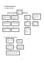
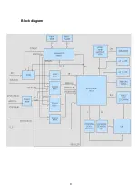
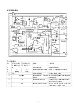
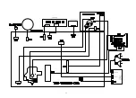
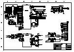
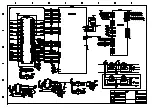
background image


8

Working principle:   

The unit adopts the super single IC R2J10165(N102) with I2C bus controlled processor produced by 
RENE

s

AS, which includes IF, color decoder, 8-bits MCU, pre-video amplify, H/V deflection, AV switch, 

audio processing, ect.. The main interfaces are: one AV IN, one S-VIDEO IN, YCbCr, one AV OUTPUT. 
 
The signal flow is below: 
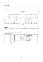
The antenna reception signal RF will be sent to the integrative tuner (contains HF and IF amplifier 
circuits), which is controlled by SDA and SCL, selects appropriate channel and sends the selected IF 
signal to the next level for processing. 
If receive the analog RF signal, RF will be sent to tuner, via HF and mixing, output IF, via V111 after, it 
sent to SAW Z101 filtering and gain better IF. Then it feed to main IC N102 (R2J10165) from 38#, 39# IF 
amplify, phase-lock loop VCO and synchronous detection, output from 34# as composite video signal 
VIF-VIDEO. After filtering, VIF-VIDEO changes to VIDEO-TV.   
If receive the digital RF signal, the signal via HF and IF amplifying, output differential digital IF signal 
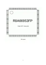
form 10#, 11#, then feed to NH07(R8A66953) demodulate and MPEG decoder, output YCbCr of 
DTV( DTV-Y and DTV-CbCr) and audio DTV-L/R. 
 
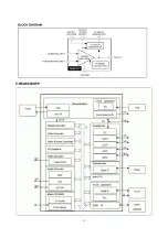
VIDEO-TV, DTV-Y, Y component from YCbCr and V/Y signal of AV1/S, AV2 selected by switch NB04 
(TC4053), they are all sent to NB01(TC4052)9#,10# select, output VIDEO, it will be sent to N102 form 
32#. C of S terminal is sent to N102 30#. Components Cb, Cr and DTV-CbCr demodulated and MPEG 
decoded by R8A66953 are sent to N102 19#,20#, then switch selection, video decoding and processing, 
it sent to the internal RGB interface matrix, pre-video amplify, contrast, bright and blacking, output RGB 
form 51#,52#,53#. After N102 internal video switch selecting, the video is sent to decoding and 
processing, it also output from 24# as AV OUT. 
The main IC N102 has the H/V deflection internal. VDRV output from 11#, via N301(TDA8172) 
amplifying to push the vertical deflection coil. HDRV output from 15#, via V301(ST1803DF) driving to 
push the horizontal deflection coil. EW-OUT output form 25# via V303(2SC3852) driving then sent to the 
horizontal deflection. 
The IF signal is sent to N102 from 38# 39# demodulating TV audio L/R. L/R of AV1/S, AV2 via audio 
switch NB04(TC4053) selecting, L/R of YCbCr and DTV-L/R demodulated and MPEG decoded by 
R8A66953, it sent to N102 29#,43# switch selection and audio process together with TV audio signal, 
then output L/R from 46# 48#, it sent to sound amplifier NV01(AN7522) amplifying to push the speaker; 
at the same time, the L/R from 46# 48# is also audio of AV OUT. 

The unit is control by the MCU built in N102, it connects tuner and E2PROM through IIC bus line and 
controls the whole unit working. 


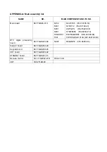
Summary of Contents for TQ2426

Page 1: ...COLOR TELEVISION TQ2426 ...

Page 2: ...utions Alignment instructions Working principle analysis of the unit Block diagram IC block diagram Wiring diagram Troubleshooting Schematic diagram APPENDIX A Main assembly list APPENDIX B Exploded view 1 2 8 9 10 15 16 18 ...

Page 3: ...parts d When replacing high power resistor keep the resistor 10 mm away from the circuit board 3 Component safety precaution Many electrical and mechanical parts in the chassis have special safety related characteristics These characteristics are often passed unnoticed by a visual inspection Replacement parts which have these special safety characteristics are identified in this manual and its sup...

Page 4: ...ment should be done Refer to picture tube adjustment method for adjustment Alignment instruction 1 Debugging item a VIF adjustment b S TRAP adjustment c H VCO adjustment d OSD adjustment e B voltage adjustment f RF AGC voltage adjustment g Focus adjustment h Screen grid voltage white balance adjustment i Field line scan center adjustment j Filed line amplitude adjustment k Raster adjustment 2 Alig...

Page 5: ... brightness check Picture and sound check Filament voltage check X ray protect check High voltage check E2 PROM copy S TRAP adjustment OSD adjustment Focus adjustment Screen grid voltage white balance adjustment Check H VCO adjustment VIF adjustment Scan amplitude center and raster adjustment B adjustment RF AGC adjustment ...

Page 6: ...r are zero b Adjust potentiometer of SCREEN till the top side seven lattices slightly light up c White balance adjustment of analog TV channel and AV channel Input erect 10 gray scale signal of VP403 at AV channel set user control to standard Adjust the center of the right third level of dark balance and the center of the left second level of bright balance Enter CRT ADJ of factory menu fixed CUT ...

Page 7: ...V 1 kV 24 27 kV 1 kV 27 29kV 1 kV 2 Set the brightness and contrast to minimum zero beam current measure the high voltage the reading should not exceed 33kV 4 2 CRT filament voltage check Receive A7 signal set picture to STANDARD use effective voltage meter to measure CRT filament voltage the reading should be 6 3 0 3 Vrms 4 3 X ray protection check 1 Receive A7 signal set user control to vivid 2 ...

Page 8: ... ON then exit the factory menu 5 1 picture menu CONTRAST 45 BRIGHTNESS 35 COLOR 45 TITN 0 SHARPNESS 30 PICTURE MODE STANDARD MORE 5 2 Volulme 30 5 3 Language English 5 4 TV mode channel 2 6 Factory menu 6 1 enter factory menu method 1 Press factory button to enter factory menu 2 Press CH or CH to select sub menu and VOL or VOL to enter 3 Press MENU to exit 6 2 the content of factory menu see table...

Page 9: ... PED 33 Y R OFSET Correction offset 30 34 YUV B ADD Correction offset 30 3 CRT ADJ 35 YUV B DEC Correction offset 30 36 ATV BRIGHT TV NTSC AV Sub bright adjustment 37 ATV CONTRAST TV NTSC AV Sub contrast adjustment 38 YUV BRIGHT COMPONENT Sub bright adjustment 39 YUV CONTRAST COMPINENT Sub contrast adjustment 40 DTV BRIGHT TV ATSC Sub bright adjustment 4 PICTURE ADJ 41 DTV CONTRAST TV ATSC Sub con...

Page 10: ...2 selected by switch NB04 TC4053 they are all sent to NB01 TC4052 9 10 select output VIDEO it will be sent to N102 form 32 C of S terminal is sent to N102 30 Components Cb Cr and DTV CbCr demodulated and MPEG decoded by R8A66953 are sent to N102 19 20 then switch selection video decoding and processing it sent to the internal RGB interface matrix pre video amplify contrast bright and blacking outp...

Page 11: ...Block diagram 9 ...

Page 12: ...10 IC Block diagram 1 R2J1016XFP ...

Page 13: ...e Ground terminal MOSFET Source and Ground 4 Vcc Power terminal Control power input 5 SS ADJ Soft Start over current protect Over current protect and Soft Start timer adjust 6 FB Feed Back terminal Timing voltage control signal input Gap oscillation control 7 BD Bottom check terminal Bottom check signal input and external Latch signal input ...

Page 14: ...udio power amplifier 4 TDA8177 Designed for monitors and high performance TVs the TDA8177 vertical deflection booster delivers flyback voltages up to 70V The TDA8177 operates with supplies up to 35V and provides up to 3App output current to drive the yoke The TDA8177 is offered in HEPTAWATT package Vcc GND ...

Page 15: ...13 5 R8A6695SFP ...

Page 16: ...14 ...

Page 17: ...15 ...

Page 18: ...coil of power The light is red press POWER can t turn on the TV Check if N102 56 output high level Check if it is X RAY protection Press POWER to turn on and the light is blue Check if N102 and N101are normal Refer to 2 and 3 Yes No Yes No No Yes Check if sound amplifier NV01 has output Speaker is damaged Check if NV01 power supply is normal if pin9 mute is high level If NV01 pin 6 and pin8 have i...

Page 19: ...V circuit works normally Check if each group voltage of FBT is normal Check CRT board and filament voltage Check if N102 has RGB output Check N102 and its periphery Check CRT board turner and its periphery If V301C output H frequency If V301 is damaged Yes Have raster No raster Abnormal Normal ...

Page 20: ......

Page 21: ......

Page 22: ......

Page 23: ...2 352 81720 20 AN7522N 352 75220 00 STRW6556 352 65560 10 ENV56M23D8F 590 40C09 00 FBT BSC26 N1013A 472 24216 00U DTV digital processing board 667 TQ2092H 69 NH07 R8A66953 353 66953 10 Side AV board 667 TQ2426H 29 Keypad board 667 TQ2426H 05 CRT board 667 TQ2092H 02 STANDBY board 667 TQ24261 05 Remote control 301 VTQ2092 21B RC V21 0B CRT 335 2512B 60 ...

Page 24: ...603 TQ24260 10 Ver 1 0 ...

Reviews: