
2
characteristics are often passed unnoticed by a visual inspection and the X-RAY RADIATION protection
afforded by them cannot necessarily be obtained by using replacement components rated for higher
wattage, etc. Replacement parts which have these special safety characteristics are identified in this
manual and its supplement electrical components having such features are shaded on the schematic
diagram and the parts list.
Before replacing any of these components, read the parts list in this manual carefully. The use of
substitute replacement parts which do not have the same characteristics as specified in the parts list
may create shock, fire, X-RAY RADIATION or other hazards.
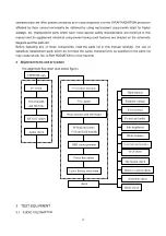
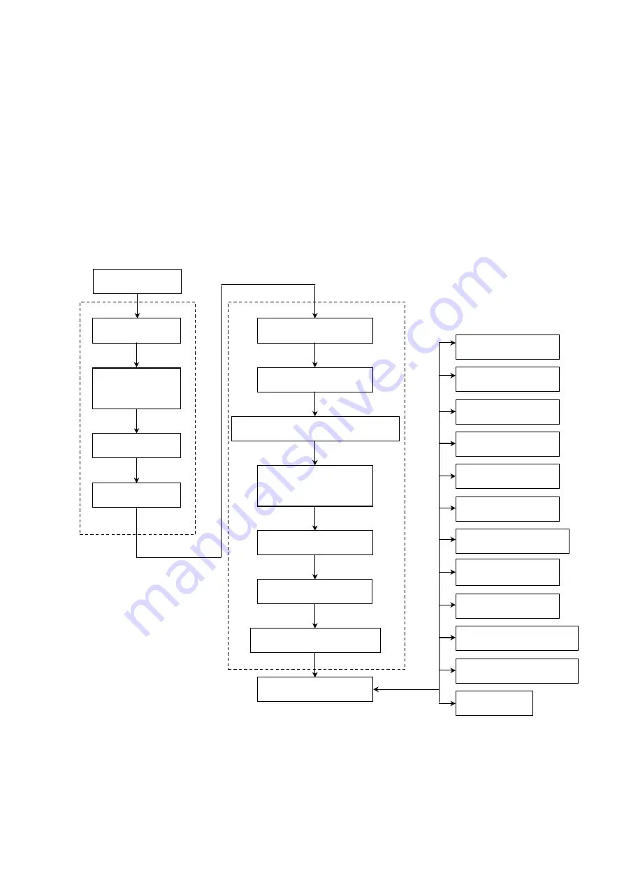
2 Alignment items and procedure
The alignment flow chart (see below figure).
3 TEST EQUIPMENT
3.1 AUDIO VOLTAMETER
EEPROM copy
B+ check
Field breadth
and field line
RF AGC adjust
Audio check
Focus adjust and aging
VG
2
adjust
White balance and sub-bright
H-field and center
field and field breadth
Leave factory state setup
OSD center position
Foucs fine adjust
check
High-handed
Filament voltage
X-ray protect
Picture and audio
Sub-brightness
White balance
Color pure and assemble
AV (S.DVD)
The button check
Remote control check
Assemble check
Safety check
Summary of Contents for TS24
Page 1: ...COLOR TELEVISION TS24 32...
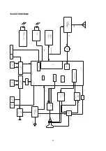
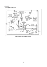
Page 11: ...10 MAIN IC LA76930 BLOCK DIAGRAM...
Page 14: ...13 FSCQ1265RT...
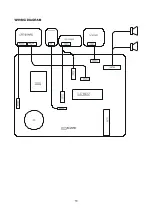
Page 15: ...14 WIRING DIAGRAM...
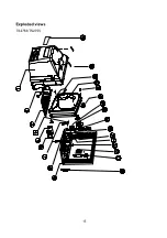
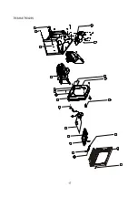
Page 16: ...15 Exploded views TS2753 TS2755...
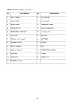
Page 18: ...17 TS3233 TS3235 14 13 12 11 10 17 15 16 18 19 20 9 8 7 6 5 4 21 22 3 2 1...


