background image

Mobile Phone Xolo Mirage Plus (Smartphone) 

Service Manual


Page 

2

 of 40


CONTENT 


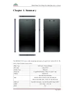
CHAPTER 1: SUMMARY .................................................................................................................... 4


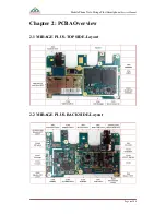
CHAPTER 2: PCBA OVERVIEW ....................................................................................................... 6


2.1


MIRAGE


PLUS-TOP


SIDE-L

AYOUT

 ............................................................................................. 6


2.2


MIRAGE


PLUS-BACK


SIDE-L

AYOUT

 ......................................................................................... 6


CHAPTER 3: EXPLANATION OF SCHEMATIC ............................................................................. 7


3.1


B

ASE 

B

AND 

C

HIP 

MSM8939


F

EATURES

.......................................................................................... 7
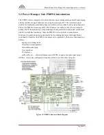
 

3.2


P

OWER 

M

ANAGER 

U

NIT 

PM8916

 INTRODUCTION

 ........................................................................... 8
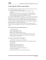
 

3.3


RF


C

HIP 

WCN3620

 DEVICE INTRODUCTION

 ................................................................................... 9


3.4


I

NTERFACE 

F

UNCTIONAL 

C

IRCUIT

 ................................................................................................. 10


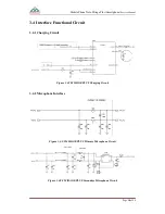
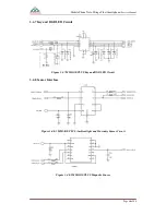
3.4.1 Charging Circuit .................................................................................................................... 10


3.4.2 Microphone Interface ............................................................................................................ 10


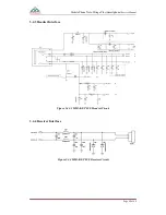
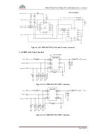
3.4.3 Headset Interface ................................................................................................................... 11


3.4.4 Receiver Interface ................................................................................................................. 11


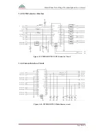
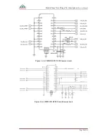
3.4.5 LCD Connector Interface ...................................................................................................... 12


3.4.6 Camera Interface Circuit ....................................................................................................... 12


3.4.7 Key and RGB LED Circuit ................................................................................................... 14


3.4.8 Sensor Interface ..................................................................................................................... 14


3.4.9 SIM Cart Tray Interface ........................................................................................................ 15


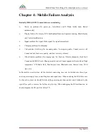
CHAPTER 4: MOBILE FAILURE ANALYSIS ................................................................................ 16


4.1


P

OWER ON ISSUE ANALYSIS

 ........................................................................................................... 17


4.2


D

ISPLAY ISSUE ANALYSIS

 ............................................................................................................... 18


4.3N

I

NCOMING 

&


O

UTGOING 

V

OICE ISSUE ANALYSIS

 ...................................................................... 19


4.4


H

EADSET ISSUE ANALYSIS

 ............................................................................................................. 21


4.5


N

O VOICE IN 

S

PEAKER ISSUE ANALYSIS

 ......................................................................................... 22


4.6


FM

 ISSUE ANALYSIS

....................................................................................................................... 23


4.7


T

OUCH 

S

CREEN ISSUE ANALYSIS

.................................................................................................... 24


4.8


C

AMERA ISSUE ANALYSIS

 .............................................................................................................. 25


Summary of Contents for MIRAGE PLUS

Page 1: ...Mobile Phone Xolo Mirage Plus Smartphone Service Manual Page 1 of 40 SERVICE MANUAL For XOLO Mirage Plus Only MOBILE TERMINAL V1 0 COMPANY CONFIDENTIAL All Rights Reserved ...

Page 2: ...CUIT 10 3 4 1 Charging Circuit 10 3 4 2 Microphone Interface 10 3 4 3 Headset Interface 11 3 4 4 Receiver Interface 11 3 4 5 LCD Connector Interface 12 3 4 6 Camera Interface Circuit 12 3 4 7 Key and RGB LED Circuit 14 3 4 8 Sensor Interface 14 3 4 9 SIM Cart Tray Interface 15 CHAPTER 4 MOBILE FAILURE ANALYSIS 16 4 1 POWER ON ISSUE ANALYSIS 17 4 2 DISPLAY ISSUE ANALYSIS 18 4 3NO INCOMING OUTGOING ...

Page 3: ...H ISSUE ANALYSIS 28 4 12 WI FI ISSUE ANALYSIS 28 4 13 GPS ISSUE ANALYSIS 29 4 14 CANNOT DOWNLOAD SOFTWARE 29 4 15 SIGNAL ISSUE ANALYSIS 30 CHAPTER 5 SOFTWARE UPGRADE GUIDANCE 31 5 1 PREPARATIONS BEFORE UPGRADE 31 5 2USB CABLE DRIVER INSTALL 32 5 3 SOFTWARE UPGRADE PROCEDURE 35 5 4 SW DOWNLOAD TROUBLESHOOTING 39 CHAPTER 6 PRODUCT EXPLODE VIEW 40 ...

Page 4: ...ils of specification shows as below Phone Type Full Touch 3 Physical Buttons OS System Android 5 0 2 Antenna Type Monopole Dimension Length Width Thickness 154mm 76 6mm 7 2 mm Platform MSM 8939 Band GSM 900 1800 1900 MHz WCDMA UMTS BAND1 2100 BAND8 900 FDD LTE BAND3 1800 TDD LTE BAND40 2300 SIM Card Dual SIM Dual online One talk Mirco SIM Nano SIM TF eMMC 16G Byte 16G Bit RAM N A ...

Page 5: ...p Key N A Back Camera Pixel 13M AF 2M FF Front Camera Pixel 5 0 Mega Fixed Focus Bluetooth Bluetooth 4 0 USB USB 2 0 WiFi YES Support Access Point PC Sync N A IrDA N A Input Method Google input SMS Yes MMS Yes STK Yes Polyphonic Melody 64 Tone Wavetable Stereo Yes Melody Format MP3 MIDI WAV AMR AAC AAC Video Format MP4 3GP Recorder Yes FM Radio Only support FM RX TV N A TV OUT N A I O Connector 5P...

Page 6: ...Mobile Phone Xolo Mirage Plus Smartphone Service Manual Page 6 of 40 Chapter 2 PCBA Overview 2 1 MIRAGE PLUS TOP SIDE Layout 2 2 MIRAGE PLUS BACK SIDE Layout ...

Page 7: ...Mobile Phone Xolo Mirage Plus Smartphone Service Manual Page 7 of 40 Chapter 3 Explanation of Schematic 3 1 Base Band Chip MSM8939 Features ...

Page 8: ... pin nanoscale package NSP that includes several ground pins for improved electrical ground mechanical stability and thermal continuity Since the PM8916 device includes so many diverse functions its operation can be understood better by studying the major functional blocks individually Therefore the PM8916 document set is organized by the device functionality as follows Input power management Outp...

Page 9: ...alcomm Atheros QCA chipsets to simplify the design cycle and reduce the OEM time to market cycle The WCN3620 IC uses low power 65 nm RF CMOS fabrication technology making it perfectly suited for battery operated devices where power consumption and performance are critical The WCN3620 device s major functional blocks are A single band WLAN RF BT radio RF and digital processing FM radio RF and digit...

Page 10: ...nual Page 10 of 40 3 4 Interface Functional Circuit 3 4 1 Charging Circuit Figure 3 4 1 MIRAGE PLUS Charging Circuit 3 4 2 Microphone Interface Figure 3 4 2 1 MIRAGE PLUS Primary Microphone Circuit Figure 3 4 2 2 MIRAGE PLUS Secondary Microphone Circuit ...

Page 11: ...obile Phone Xolo Mirage Plus Smartphone Service Manual Page 11 of 40 3 4 3 Headset Interface Figure 3 4 3 2 MIRAGE PLUS Headset Circuit 3 4 4 Receiver Interface Figure 3 4 4 MIRAGE PLUS Receiver Circuit ...

Page 12: ...e Xolo Mirage Plus Smartphone Service Manual Page 12 of 40 3 4 5 LCD Connector Interface Figure 3 4 5 MIRAGE PLUS LCD Connector Circuit 3 4 6 Camera Interface Circuit Figure 3 4 6 1 MIRAGE PLUS Main Camera circuit ...

Page 13: ...Mobile Phone Xolo Mirage Plus Smartphone Service Manual Page 13 of 40 Figure 3 4 6 2 MIRAGE PLUS 3D Camera circuit Figure 3 4 6 3 MIRAGE PLUS Front Camera circuit ...

Page 14: ...Service Manual Page 14 of 40 3 4 7 Key and RGB LED Circuit Figure 3 4 7 MIRAGE PLUS Key and RGB LED Circuit 3 4 8 Sensor Interface Figure 3 4 8 1 MIRAGE PLUS Ambient light and Proximity Sensor Circuit Figure 3 4 8 2 MIRAGE PLUS Magnetic Sensor ...

Page 15: ...irage Plus Smartphone Service Manual Page 15 of 40 Figure 3 4 8 3 MIRAGE PLUS Gyro and G sensor connector 3 4 9 SIM Cart Tray Interface Figure 3 4 9 1 MIRAGE PLUS SIM 1 Interface Figure 3 4 9 2 MIRAGE PLUS SIM 1 Interface ...

Page 16: ...ial out Bad voice quality and Low receiving volume Other Function problem No ringing tone No vibration Vibrator abnormity Clock fault Cannot read SIM T F card Phone password locked Cannot upgrade software Show high temperature FM Radio fault Touchscreen issue Bluetooth issue Camera issue Wi Fi issue etc In the mobile circuit system all the electrical connecting trace can be divided into three type...

Page 17: ... not if it is abnormal replace it completed all above steps you still cannot solve this issue please follow the next steps 2 No power on Current If the mobile phone can t powered on by battery we can use the DC Power Supply to check the mobile phone s power on current After connect mobile phone with DC Power Supply press power on key then check the current value For No current 0mA issue it means p...

Page 18: ...mal Replace CPU U600 Replace CPU U600 End End Resolder replace Resolder replace N N N N Y Y Upgrade firmware Upgrade firmware Y Y Replace LCD Replace LCD Is the relevant component normal Is the relevant component normal N N Y Y Replace the component Replace the component Figure 4 2 Display failure repair process Upgrade new software for the mobile phone MIRAGE PLUS s LCD is connected to mainboard ...

Page 19: ...ing Voice issue analysis No received voice Is audio setting normal Adjust setting Is receiver connect contact point normal Clean or adjust receiver Is receiver normal Replace receiver Repair audio circuit End Y Y Y N N Upgrade firmware N Figure 4 3 1 No received voice failure repair process ...

Page 20: ... Upgrade the latest firmware and try again Check the phone call volume is OK or not Check if the connection of receiver is ok or not Measure the resistance of receiver and check if it s normal the standard value should be 32 ohm For outgoing no voice failure You can enter into Factory Mode by keep press Power on key volume key the same time Select Audio Handset and blow at main microphone the echo...

Page 21: ...er or replace J800 Resolder or replace J800 N N Y Y Upgrade firmware Upgrade firmware Resolder or replace U300 Resolder or replace U300 N N Replace CPU U600 Replace CPU U600 Is power supply normal Figure 4 4 Headset failure repair process This issue often occurs in a mobile phone You can enter into Factory Mode by keep press Power on key volume key the same time Select 14 Audio Headset and you wil...

Page 22: ...CONN Replace FPC or CONN N N Y Y Replace CPU U600 Replace CPU U600 Resolder or replace U300 Resolder or replace U300 N N Is power supply normal Y Y Y Y Figure 4 5No voice in speaker failure repair process Check whether the audio source can output from baseband chip with a headset Then check speaker resistance to confirm whether the resistance of Speaker is 8ohm If not it means the speaker is broke...

Page 23: ...lure repair process Upgrade new software for the mobile phone Check Headset already insert to Mobile phone or not Enter into Factory Mode by keep press Power on key volume key the same time Then go to 35 FM Click Search Next to change the radio channel If the FM function is OK you will hear the FM channel voice If the FM cannot work well you can check FM power supply path FM clock signal path WTR4...

Page 24: ...solder or replace FPC connector N Y Upgrade firmware Is the power supply normal Replace U300 Figure 4 7 TP failure repair process Upgrade new software for the mobile phone Check FPC and TP connector J901 If problem still not solved you need to replace a new TP or CPU U600 After repaired enter into Factory Mode by press Power on key volume key the same time Go to 18 Touch Test TP function ...

Page 25: ...PC connector N N Y Y Upgrade firmware Upgrade firmware Check if the power supply OK Check if the power supply OK Replace U300 Replace U300 N N Y Y Figure 4 8 Camera failure repair process Upgrade new software for the mobile phone Replace camera module and test it again If problem still not solved you need to follow the product circuit diagram to check the corresponding components and CPU U600 Afte...

Page 26: ...Y Upgrade firmware Figure 4 9 Vibrator failure repair process Upgrade new software for the mobile phone Check Vibrator Replace Vibrator and test it again If problem still not solved you need to follow the product circuit diagram to corresponding components After repaired enter into Factory Mode by press Power on key volume key the same time Select 11Vibrator and then you can test the function ...

Page 27: ... firmware Is Switching Charger U101 PMU U303 OK Is Switching Charger U101 PMU U303 OK Resolder or replace U101 U300 Resolder or replace U101 U300 Y Y N N Figure 4 10 Charging failure repair process Upgrade new software for the mobile phone Check Battery and Charger Check Battery Connector J100 USB Connector Replace the Switching charger U101 or PMU U300 and test it again If problem still not solve...

Page 28: ...software for the mobile phone Check BT ANT Clean or Replace the BT ANT and test it again If problem still not solved you need to follow the product circuit diagram to check BT PA U1103 After repaired enter into Factory Mode by press Power on key volume key the same time select 36 Bluetooth and then you can test the function 4 12 Wi Fi issue analysis WiFi failure Repair WiFi circuit End Is WiFi ant...

Page 29: ...ormal Replace ANT N Y Upgrade firmware Figure 4 13 GPS failure repair process Upgrade new software for the mobile phone Check the connection of GPS ANT Clean or Replace the GPS ANT and test it again If problem still not solved you need to follow the product circuit diagram to check U1103 and corresponding components After repaired enter into Factory Mode by press Power on key volume key the same t...

Page 30: ... circuit End Y Is RF parameter normal Re calibrate RF Is RF ANT normal Replace RF ANT N Y N Upgrade firmware Figure 4 15 Signal failure repair process RF failure often occurs in calibration or capability test the best diagnostic method is to use wireless universal tester spectrum analyzer and signal source matched with META tool to test it Corresponding components including Antenna switch Saw filt...

Page 31: ...ry for MIRAGE PLUS It gives the power to Mobile phone Smart phone Flash Tool QDownload150416 QCUSB_Driver USB Driver for Smart phone USB Data Cable USB Driver Installer must be installed Personal Computer PC Recommended PC HW requirements Computer processor Pentium 700 MHz or higher RAM 256 MB or higher Disk space 100 200 MB or higher Supported operating systems Windows 2000 Service Pack 3 or high...

Page 32: ...able Driver Install MTK USB Port Driver Install Step 1 Find the file of QCUSB_Driver package path and then run the QCUSB_Driver Attention Do not connect the cable with PC when you install the USB Driver Figure 5 2 1 QCUSB_Driver Package Figure 5 2 2 USB driver installing progress ...

Page 33: ... below Figure 5 2 3 USB Data Cable Connect Structure Step 3 Power off the Smart phone Press power volume the same time for 3s the device will vibrated a short time and then connect USB Data cable with Smart phone PC screen will pop up some message you need to waiting for few minutes The figure shows as below After new driver installed successfully disconnect the Smart phone with USB Data cable ...

Page 34: ...lo Mirage Plus Smartphone Service Manual Page 34 of 40 Figure 5 2 4 USB Data Cable Connect Structure The COM port will appear shortly in device manager as below picture Figure 5 2 5 Virtual COM port in device manager ...

Page 35: ...Otherwise the handset s memory will be broken by the unfinished upgrade process and cause the handset cannot be powered on Step 1 double click the executable file QDownload to run the flash tool the first time to run the tool an error prompt will pop up just click OK to ignore it The flash tool interface is as below Figure 5 3 1 Smart Phone Flash Tool Download window Step 2 click the icon Browser ...

Page 36: ...ge Plus Smartphone Service Manual Page 36 of 40 Figure 5 3 2 Choose MT6582_Android_scatter file Step3 Click Load XML as below figure to choose rawprogram_unsparse_without_QCN Figure 5 3 3 Select RawProgram File 1 2 3 1 3 2 1 ...

Page 37: ...ure 5 3 3 Select Patch File 2 Step 4 Power off the handset Press power volume keys the same time for 3s the handset will vibrate a while and the screen will blink one time and then connect to PC with USB cable click Download Figure 5 3 4 Connect to PC and Start Download 1 2 ...

Page 38: ...rvice Manual Page 38 of 40 Step 5 The upgrade procedure will start automatically as below picture Figure 5 3 5 Firmware upgraded progress Step 6 Once download success the prompt will pop up as below picture Figure 5 3 6 Firmware upgraded success ...

Page 39: ...on When download successfully the indicate icon will be Green and there s PASS in the description if download fail the indicate icon will be Red and there s Fail in the description Case two What should we do when the downloading process is completely Solution You should check if the IMEI is existed Otherwise you should re write the IMEI The code to check the IMEI 06 ...

Page 40: ...01 Screen Protection Film 09 Buttons Limit Steel Disc 17 Front CAM 02 TP Module 10 Fix Steel Disc 18 Battery 03 LCD Module 11 Main Mic Cover 19 Main ANT SPK 04 Front Case Module 12 Main FPC Module 20 GPS ANT Diversity ANT 05 RF Cable 13 SIM Card Tray 06 Volume 14 Sub Mic Cover 21 Battery Cover 07 Volume 15 Rear CAM Module 22 Battery Cover Protection Film 08 Power Key 16 PCBA ...

Reviews: