Jacks, Switches and Pots
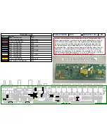
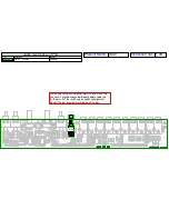
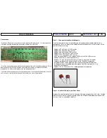
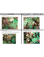
You may want to test fit the rear panel to
make sure they are aligned good enough.
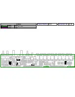
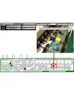
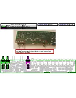
Next you can solder the rear solder pad for each of the jacks.
Make sure the jack is seated properly before soldering. Hold
down the jack firmly while soldering so that it seats properly.
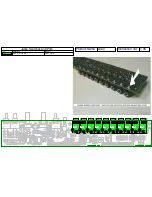
Next you can go back and re-heat the front pads and add more solder,
then solder in the third pad for each jack and everything should look ok.
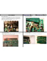
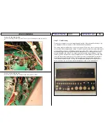
Now is a good time to clean your PCB. If you’re using ordinary 60/40
rosin core solder you probably have a lot flux residue. Cleaning pcb’s
is a whole art form in itself. Your best bet is to use a flux remover
spray or denatured alcohol and a brush. A boar’s hair brush is what is
typically used.
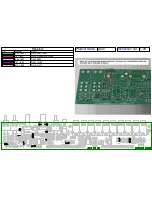
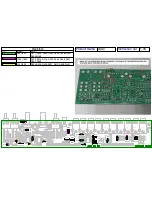
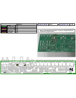
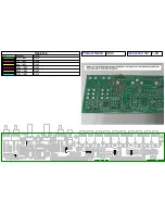
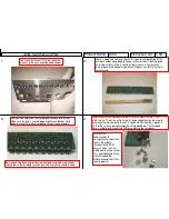
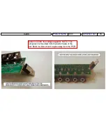
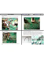
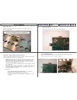
Install the (3) small L-brackets to the PCB as shown. Use the 11/32”
4-40 screws. There’s an extra screw in the package that can be used to
help align the bracket while the nut is tightened. Position the L-brackets
so that the screw is going through the unthreaded hole. The threaded
hole is used later to mount the PCB assembly to the rear panel.
1.06
Instruction Ver.
x0xio
Product Name
1.
2.
3.
4.
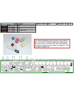
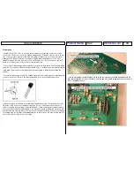
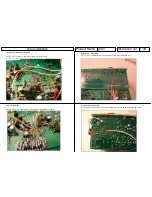
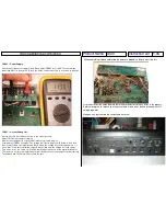
IMPORTANT:-
Make sure not to
over-tighten the screw that
mounts the middle
L-bracket to the PCB,
there is a trace that runs
underneath that screw and
if it is over-tightened it may
scratch through the
soldermask and short that
trace to ground.


