9
6. Front/Back Panel
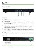
6.1 Front Panel
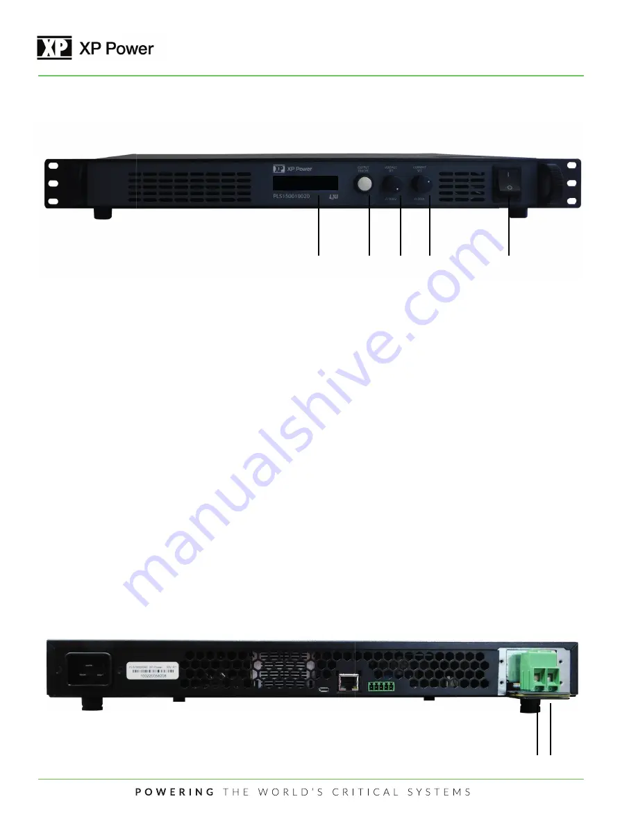
(1)
Power Switch:
Please consult “Cautions Before Using” section before turning on power switch.
(2)
Current Rotary Control:
Turn clockwise to increase current limit setting. Turning slowly will increment the least significant digit of the displayed
setting. As the control is turned faster more significant digits will be incremented. When the output is activated pressing
this control will display Set Current.
(3)
Voltage Rotary Control:
Turn clockwise to increase voltage limit setting. Turning slowly will increment the least significant digit of the displayed
setting. As the control is turned faster more significant digits will be incremented. When the output is activated
pressing this control will display Set Voltage.
(4)
Output On/Off Button:
Pushing this button after the power to the power supply has been turned on enables the output voltage. Pressing and
holding this button for more than 5 seconds and then releasing will put the power supply into Setup mode. See section
8.2 for setup instructions.
(5)
Display:
16 character by 2 line display. This display shows set points, actual operating values, power supply operating status,
error messages, and setup information.
6.1 Back Panel
1
2
3
4
5
ON VMODE I
OC
V=100.0 I=0.750
7 6
(6)
Negative Output Terminal
(7)
Positive Output Terminal


