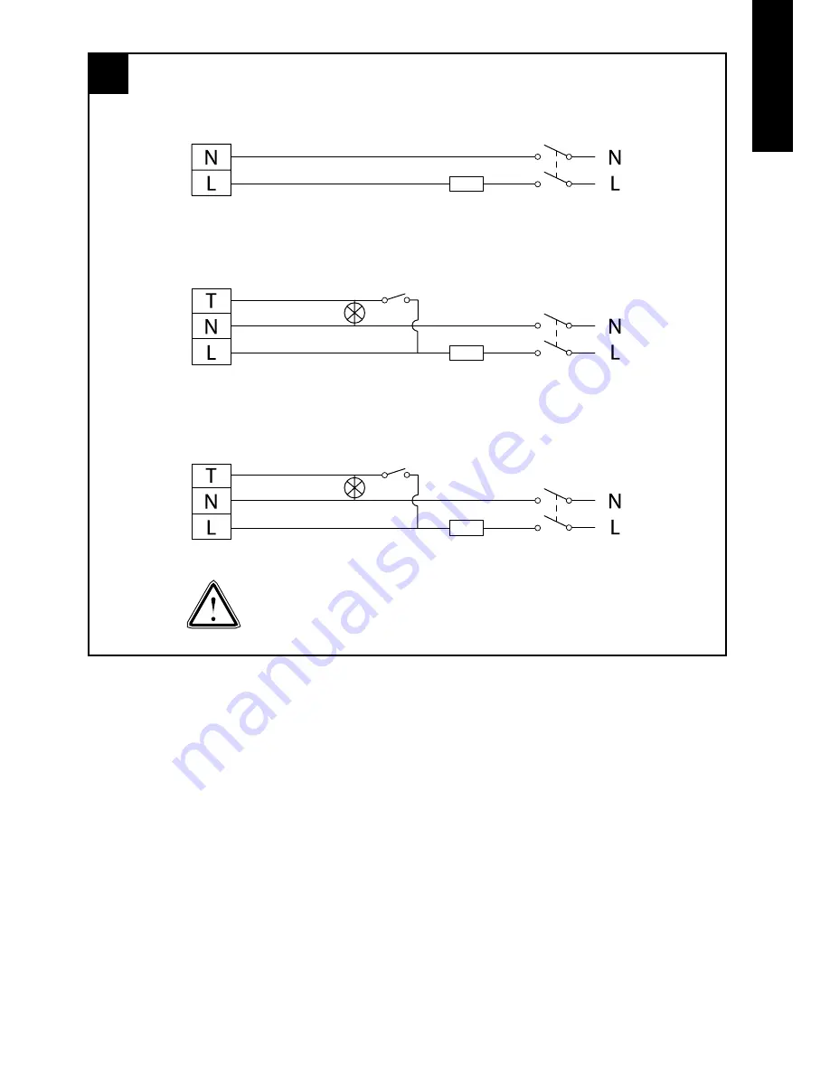
Wire the electrical connections.
11. Make sure the mains supply is isolated.
Switch off the mains electrical supply and
remove fuses.
12. Feed the cable to the terminal block. Wire
the fan as shown in Figure E using the
diagram appropriate to the fan model.
13. Connect the cable from the isolating switch
to the electrical supply wiring.
Fan Settings
SPEED SETTING
The fans are factory set to low speed, but have
two speed settings for different applications.
Select either high or low speed by connecting
the jumper between the centre and high or low
speed pin on the jumper (see Figure D1 & D2).
DX100BTR / DX100BTS Only.
• To adjust the over-run period turn the control
(T) clockwise to increase and anti-clockwise
to decrease – see Figure D1.
DX100BHTR / DX100BHTS / DX100BHPTR /
DX100BHPTS only – see figures C and D.
• The pre-set humidity operation is factory set
at approximately 75% Relative Humidity (RH),
but can be adjusted between 65% and 85%
RH by control H.
• The over-run timer is factory set at 15 minutes
but can be adjusted from 30 seconds to 30
minutes by control T.
• Turn the controls clockwise to increase RH or
time and anti-clockwise to decrease.
English
DX100BR/DX100BS
DX100BPR/DX100BPS
DX100BTR/DX100BTS
DX100BHTR/DX100BHTS
DX100BHPTR/DX100BHPTS
E
FAN
TERMINALS
FAN
TERMINALS
FAN
TERMINALS
DOUBLE POLE
ISOLATING SWITCH
DOUBLE POLE
ISOLATING SWITCH
DOUBLE POLE
ISOLATING SWITCH
ON/OFF
SWITCH
(OPTIONAL)
ON/OFF
SWITCH
(REQUIRED)
LAMP
(IF REQUIRED)
LAMP
(IF REQUIRED)
FUSE
FUSE
FUSE
For fixed wiring circuits the protective fuse
for the appliance must not exceed 5A.


