background image


This  electrical  product,  if  installed  in  a  shower 
room  or  bathroom,  must  be  situated  so  it 
cannot  be  touched  by  persons  making  use  of 
the bath or shower. 


1.  Check  that  there  are  no  buried  pipes  or 

cables  (e.g.  Electricity,  gas,  water)  behind 
the  switch  location  (in  the  wall  or  above 
the ceiling). 

2.  Lay  in  the  cable  from  the  isolating  switch  to 

the fan location via the on/off switch (see Fig. 
E.  

3.  Lay  in  the  cable  from  the  isolating  switch  to 

the  point  of  connection  to  the  mains  supply. 

WARNING: 

DO 

NOT 

MAKE 

ANY 

CONNECTIONS  TO  THE  ELECTRICITY 
SUPPLY AT THIS STAGE.


4.  Install  the  isolating  switch  and  the  on/off 

switch, see Fig. E. 

5.  Make  all  connections  within  the  isolating 

switch, and the on/off if required. 


Note:  When  installed  in  a  bathroom  all  switches 
must  be  of  a  pull  cord  type  and  must  be  situated 
so  that  they  can  not  be  touched  by  persons 
making use of the bath or shower. 


These  models  are  permanently  connected  to  the 
supply  and  operation  is  controlled  by  a  remote 
switch.  Wire  directly  to  the  supply  through  an 
approved 10A wall mounted surface switch with at 
least 3mm clearance between contacts. 
 
 
If  working  above  ground  level,  appropriate  safety 
precautions must be observed. 
WARNING:  EYE  PROTECTION  MUST  BE  WORN 
DURING 

ALL 

DRILLING 

AND 

CHISELLING 

OPERATIONS. 


1.  Check there are no buried pipes or cables 

in  a  wall  or  obstructions  on  the  outside 
(e.g. Electricity, gas, water). 

2.  Ensure  that  the  centre  of  the  hole  is  located 

at  least  145mm  from  the  edges  of  the  wall, 
see Fig. A. 

3.  Mark on the centre of the duct hole. 
4.  Use this centre to draw a circle to suit the wall 

duct  (203mm  diameter  for  a  WK6/300  or 
WK6/450). 


5a. 

Use 

as 

directed 

by 

the 

core 

drill            


manufacturer. 


5b. Drill a centre hole right through the wall. 
6.  Cut the hole. Do not cut right through the wall 

(the  recommended  method  is  to drill  a  series 
of  holes,  close  together,  around  the  edge  of 
the cutting line and remove the brick between 
the holes with a chisel). 

7.  Go  outside  and  cut  a  hole  in  the  outer  wall, 

repeating the process described above. 

8.  Fit  the  ducting.  Ensure  that  the  duct  slopes 

down  away  from  the  fan  to  allow  drainage  of 
any incoming rain water to the outside. 

9.  Make  good  the  hole.  Allow  for  the  mortar  to 

set before continuing with the installation. 


Obtain a ready cut pane with a correctly located hole, 
184mm diameter, see Fig. A. 


1.  For  window  mounting,  use  the  two  short 

ladder strips supplied with the fan. 


For  wall  mounting,  use  the  longer  ladder 


strips  supplied  with  the  wall  kit  WK6/300  or 


WK6/450. 

2.  Secure the two ladder strips to the outer grille 

by  positioning  them  over  the  hook  moulding 
and snapping them into position. 

3.  Ensure after fitting the hook moulding that the 

gasket is in the correct position, see Fig. B. 

4.  Insert  the  two  screw  covers  in  the  two  fixing 

holes in the outer grille. 


If  working  above  ground  level,  appropriate  safety 
precautions must be observed. 

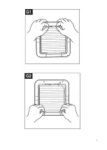
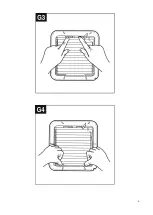
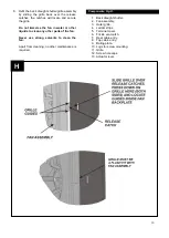
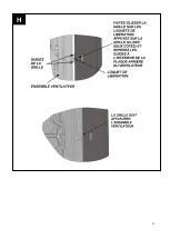
Remove  the  back  draught  shutter/grille  assembly  by 
pressing  the  release  catches  located  on  the  sides  of 
the  unit  with  a  6mm  screwdriver  or  a  coin,  whilst 
pulling the grille forward. 


1.  Hold  up  the  outer  grille  to  the  outside  wall  or 

window  so  that  the  hole  in  the  outer  grille  is 
aligned with the hole in the wall or window. 

2a. 

If  wiring  from  the  rear,  remove  the  fan’s 


terminal cover and rear entry knockout. Feed 


the cable through the rear cable entry. 

2b. 

If  wiring  from  above,  remove  the  fan’s 


terminal cover and feed the cable through the 


top cable entry. 

3.  Hold the fan assembly to the inside of the wall 

or  window  and  guide  the  ladder  strips  from 
the  outer  grille  through  the  slots  in  the  fan 
assembly. 

4.  Insert  the  slotted  screws  into  the  pockets 

around the ladder strip slots. 

5.  Tighten  the  screws  carefully  to  make  a  good 

seal, do not over tighten the screws. 

6.  Trim  the  ladder  strips  back  to  the  required 

length, if necessary remove any sharp edges. 


1.  Hold  the  outer  grille  up  to  the  outside  of  the 

wall  so  that  the  hole  in  the  outer  grille  is 
aligned with the hole in the wall. 

2.  Mark  the  positions  of  the  fixing  holes  in  the 

top right and bottom left corners. 

3.  Drill the holes and insert anchor fixings to suit 

the wall. 

4.  Screw  the  outer  grille  securely  in  place. 

Do 

not over tighten screws.


For Australia only 


Preparing the hole 

If installing in a wall 


If core drill equipment is available 


If core drill equipment is not available 


If installing in a window 


Preparing the fan for installation 

Mounting the fan in the hole, Fig. C. 

If installing with ladder strips 


If using screw fixings 


Installing the switches and cables 

Summary of Contents for GX6EC

Page 1: ...1 Internal External Wall Window Fan Range GX6EC 071262 GXC6EC 071279 Installation and maintenance instructions Retain for future reference...

Page 2: ...2 A...

Page 3: ...3 D C...

Page 4: ...4 E...

Page 5: ...5...

Page 6: ...6...

Page 7: ...r and No 1 and 2 Pozidriv screwdrivers A single glazed window with a minimum glass thickness of 4mm or a double glazed unit with a pre prepared sealed hole Masonry drill hammer and chisel or core dril...

Page 8: ...e good the hole Allow for the mortar to set before continuing with the installation Obtain a ready cut pane with a correctly located hole 184mm diameter see Fig A 1 For window mounting use the two sho...

Page 9: ...delay ensures quiet operation except GXC6EC model For Australia Only Warning Children should not play with the appliance Young children and the infirm should be supervised The fan is operated by an i...

Page 10: ...liquids to clean any other parts of the fan Never use strong solvents to clean the fan Apart from cleaning no other maintenance is required 1 Back draught shutter 2 Fan assembly 3 Outer grille 4 Ladde...

Page 11: ...ements de mise la terre doivent tre respect s C ble circulaire 2 conducteurs d un minimum de 0 75 mm avec un diam tre d au moins 5 5 mm le produit est doublement isol et ne n cessite pas de mise la te...

Page 12: ...EMENT VOUS DEVEZ PORTER UNE PROTECTION OCULAIRE LORS DE TOUTES LES OP RATIONS DE FORAGE ET DE BURINAGE 1 V rifiez qu il n y a aucun tuyau ou c ble enfoui dans le mur ou obstruction l ext rieur par ex...

Page 13: ...omme avant et vissez les solidement en place Ne serrez pas trop les vis Remarque Pour des installations particuli rement difficiles il est possible de fixer le ventilateur avec une combinaison de fixa...

Page 14: ...t tirez l obturateur vers l avant voir les figures G1 et G2 3 Pour nettoyer la roue essuyez la avec un chiffon humide non pelucheux N utilisez pas de d tergents puissants ou de produits de nettoyage c...

Page 15: ...15 H...

Page 16: ...eachten Rundes 2 adriges Kabel mit einem Durchmesser von mindestens 0 75 mm und einem Durchmesser von mindestens 5 5 mm Produkt ist doppelt isoliert und ben tigt keine Erdung Gro er Schraubendreher mi...

Page 17: ...emessene Sicherheitsma nahmen zu befolgen WARNUNG BEI ALLEN BOHR UND STEMMARBEITEN MUSS EIN AUGENSCHUTZ GETRAGEN WERDEN 1 berpr fen Sie dass sich keine verborgenen Rohre oder Kabel in einer Wand oder...

Page 18: ...Wenn Sie die Verkabelung von oben vornehmen entfernen Sie die Klemmenabdeckung des L fters Machen Sie ein Loch durch die T lle das geeignet ist um einen festen Sitz um den Kabelmantel zu gew hrleiste...

Page 19: ...rehen und der angetriebene Verschluss sich schlie en kann Die Reinigung am GXC6EC kann beginnen sobald sich das Fl gelrad nicht mehr dreht 2 Entfernen Sie die R ckzugverschluss Gitter Baugruppe indem...

Page 20: ...20 H...

Page 21: ...tte schroevendraaier 3mm platte elektricien schroevendraaier en Nr 1 en 2 Pozidriv schroevendraaiers Enkelglas raam met een minimum glasdikte van 4mm of een dubbelglas unit met een van tevoren verzege...

Page 22: ...r de muur de aanbevolen methode is om een reeks dicht bij elkaar liggende boorgaten te maken rond de rand van het kapprofiel en de steen tussen de boorgaten weg te kappen met een beitel 7 Ga naar buit...

Page 23: ...ven druk deze in aan de zijkanten van het rooster zoals getoond in Afb H en plaats de voelers op het rooster in de achterplaat van de ventilator De sluitingen op de achterplaat zullen het rooster op d...

Page 24: ...t rooster schoon in warm zeepwater Gebruik geen sterke detergenten of chemische reinigers 5 Droog de achterste tochtafsluiter en het rooster grondig en plaats de achterste tochtafsluiter op het rooste...

Page 25: ...25 This page has been left blank for the addition any notes you may wish to make H...

Page 26: ...sa a terra Cavo bipolare circolare di un minimo di 0 75mm con un diametro non inferiore a 5 5mm il Prodotto ha un doppio isolamento e non richiede una messa a terra Cacciavite a taglio svasato 6mm cac...

Page 27: ...SERE INDOSSATI DURANTE TUTTE LE OPERAZIONI DI FORATURA E SCALPELLATURA 1 Controllare che non vi siano cavi o condutture all interno di una parete od ostacoli al suo esterno ad es elettricit gas acqua...

Page 28: ...9 Rimuovere il gruppo della ventola effettuare fori e inserire le viti di fissaggio adatte al tipo di parete 10 Riposizionare il cavo e il gruppo della ventola come in precedenza e stringere accuratam...

Page 29: ...a moneta tirando contemporaneamente la griglia in avanti Per rimuovere la serranda anti ritorno mettere l apparecchiatura rivolta verso il basso e tirare la serranda in avanti vedere Fig G1 e Fig G2 3...

Page 30: ...30 H...

Page 31: ...amt stjernetrekker Pozidrive nr 1 og nr 2 Et vindu med enkel glassrute som er minst 4 mm tykk eller et vindu med dobbel glassrute med et klargjort forseglet hull Murbor hammer og meisel eller kjernebo...

Page 32: ...t fra viften slik at regnvann dreneres til utsiden 9 Tett hullet La m rtelen t rke f r du fortsetter med installasjonen Ankaff en glassrute hvor det er kuttet et hull med en diameter p 184 mm p riktig...

Page 33: ...eren og gir stilleg ende drift unntatt GXC6EC modellen Kun for kunder i Australia Advarsel Barn m ikke leke med viften Sm barn og utsatte svake personer m v re under tilsyn Viften sl s av p med en int...

Page 34: ...en Bortsett fra rengj ring er det ikke n dvendig med annet vedlikehold 1 Kaldrasspjeld 2 Vifteenhet 3 Utvendig rist 4 Stigestrips 5 Terminaldeksel 6 Haspe for naturlig ventilasjon 7 Kabelinngang bak 8...

Page 35: ...35 Xpelair GX6EC GXC6EC 8 2 0 75mm 5 5mm 6mm 3mm Pozidriv 1 2 4mm WK6 300 pelair 300mm 12 WK6 450 Xpelair 450mm 18 4 8 x 38mm Pan 145mm A GX6EC GXC6EC...

Page 36: ...36 50 C Xpelair 1 2 E 3 4 E 5 10A 3mm 1 2 145mm A 3 4 203mm WK6 300 WK6 450 5 5 6 7 8 9 184mm A 1 WK6 300 WK6 450 2...

Page 37: ...37 3 B 4 6mm 1 2 2 3 4 5 6 1 2 3 4 5 6 6 7 8 9 10 1 E 2 C 3 4 5 H 6 7 8 5 C...

Page 38: ...38 1 3 GXC6EC 1 2 3 F 6 4 5 1 3 GXC6EC 2 6mm G1 G2 3 4 5 G3 G4 6 1 2 3 4 5 6 7 8 9 10 11 12 13 GXC6EC GX6EC D...

Page 39: ...39...

Page 40: ...40 Xpelair GX6EC GXC6EC 8 145 50 Xpelair 1 2 3 4 5 GX6EC 0 75 5 5 8 3 1 2 Pozidriv 4 WK6 300 Xpelair 300 12 WK6 450 Xpelair 450 18 4 8 38 GX6EC GXC6EC...

Page 41: ...41 3 4 5 6 1 2 3 4 5 6 2 6 b 7 8 9 10 1 2 3 4 5 6 7 8 5 3 GXC6EC 10 3 1 2 145 3 4 203 WK6 300 WK6 450 5 5 6 7 8 9 184 1 WK6 300 WK6 450 2 3 4 6 1 2 2...

Page 42: ...42 1 2 3 4 5 6 7 8 9 10 11 12 13 1 2 3 6 4 5 1 3 GXC6EC 2 6 1 2 3 4 5 3 4 6 GXC6EC GX6EC...

Page 43: ...43...

Page 44: ...Xpelair or its authorised dealers Caused by repairs or alterations to your Xpelair product not carried out by Xpelair service personnel or its authorised dealer s Caused by use of any consumables or...

Reviews: