background image

Inside installation of the finisher ring 

Proceed as follows:

i)

Push the large tube through the hole so it extends some 50mm beyond the face of the outside wall.

ii)

Apply silicon mastic around the rear face of the split finisher – do not compress the adhesive.

ENSURE EXTERIOR BRICKWORK IS DUST FREE

iii)

Grip the finisher in your right hand, (palm uppermost) at the left hand end of the split with the adhesive side
facing you and the split at the top. Pull back the right hand end of the split along your right arm with your left
hand. Push the finisher right through the large tube and let it expand again. Don’t let go !

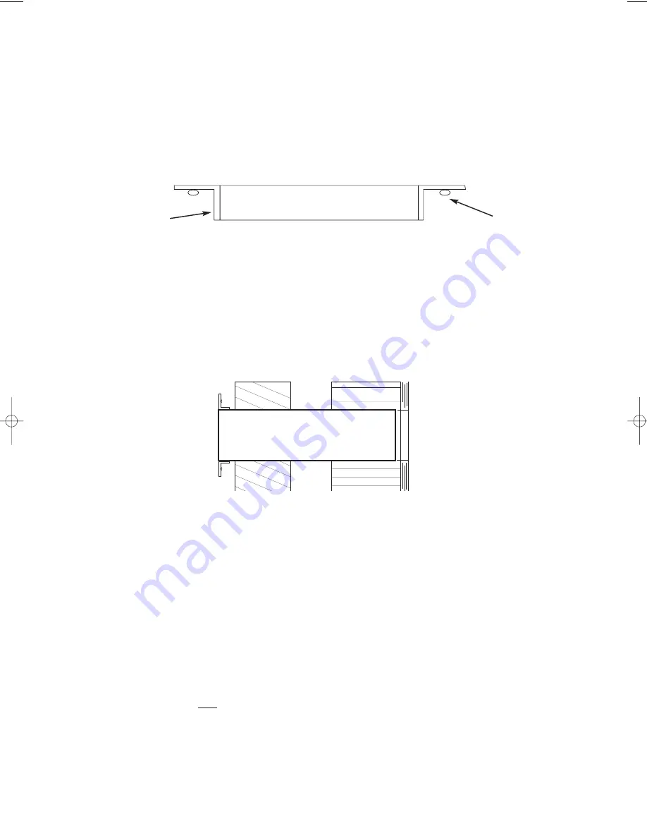
With your right hand, place the inner flange on the outside of the large tube. Move your fingers in an
anticlockwise direction until the finisher is pushed fully onto the tube (see below)

iv)

Then, pull the tube and finisher back towards the room making sure that the split remains at the bottom. Carefully
pull the finisher into the gap between tube and brickwork. Press the adhesive gently against the wall, compressing
the adhesive. Then pull the tube into the room leaving the finisher in place. Ensure that the finisher does not fall.

v)

Now manipulate the finisher to expand it outwards and increase it’s internal diameter as much as possible. This
will assist the re-entry of the tube. Compress the adhesive fully against the wall to hold it in position.

h)

Fit the outside cowl to your prepared length of tube using PVC adhesive such as 

Bostik PVC Pipe Weld

or

similar. Place the adhesive in an even layer around the inside diameter of  the tube at the end that you did not cut.
Place the outside louvred vent on the end of the tube and allow the glue to set before handling it again. Wipe off
any excess adhesive on the outside of the cowl.

i)

It is important for the correct operation that the smaller diameter tube is the correct length. This tube connects the
extraction fan housing to the outside cowl and separates the two air streams. The correct fitting of this tube is
critical to the efficient operation of the ventilator. To achieve this, whatever length has been cut off the outer tube,
the exact same length must be cut off the inner tube. 

5

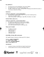
ADHESIVE

INNER  FLANGE

Eclipse - Oxplaire  12/4/00  6:51 pm  Page 5

Summary of Contents for XHR150HP

Page 1: ...reduce dust mite eliminate mould growth or dampness and condensation and to provide warmed fresh air April 2000 These appliances are intended for connection to fixed wiring Check that the electrical rating shown on the transformer matches the mains supply All installation must be supervised by a qualified Electrician Installation and wiring must conform to current IEE Regualtions UK local or appro...

Page 2: ...can be adjusted by turning the thumbwheel as shown on page 2 We recommend that it is initially set to number 6 on the scale which is suitable for most locations Turning the thumbwheel clockwise decreases the sensitivity fan in boost for shorter time and anti clockwise increases the sensitivity fan in boost for longer time To prevent tampering with the setting after installation the thumbwheel can ...

Page 3: ...tric Requirements of all authorities concerned must be observed for exhaust air discharge and intake flow rates a Survey the property carefully and identify the best site for the ventilator Condensation problems dampness and mould growth are stimulated by high levels of humidity the source of which can be the bath shower room laundry room kitchen or possibly a damp wall Identify an area in the roo...

Page 4: ... masonary does not fall injure people or damage property below e Measure the length of the hole between the outside brick face and inner plaster work Now cut the outer tube accurately to the required length The length should be 4mm greater that the length of the hole x but no less that 254mm otherwise the Heat Exchanger will not fit Carefully mark the tube all round and cut with a hacksaw and fini...

Page 5: ...sive gently against the wall compressing the adhesive Then pull the tube into the room leaving the finisher in place Ensure that the finisher does not fall v Now manipulate the finisher to expand it outwards and increase it s internal diameter as much as possible This will assist the re entry of the tube Compress the adhesive fully against the wall to hold it in position h Fit the outside cowl to ...

Page 6: ... or in the direction you have determined for the transformer or remote control Fit screw plugs into the screw holes l Fit the wall plate onto the open end of the large tube fitted with the outside cowl Measure the distance from the back edge of the wall plate to the other end of the tube The tube should not extend beyond the outside wall finisher Use the PVC weld adhesive to stick the wall plate t...

Page 7: ...uble isolating switch with a minimum contact gap of 3mm wall or ceiling mounted If metal switch boxes are used earthing regulations must be following Suitably rated 2 core cable 3 mm electricians screwdriver and No 1 or No 2 pozidrive screwdrivers Masonry drill hammer chisel or core drill equipment if available Mortar to make good the hole if required Decide how you are going to run the wires from...

Page 8: ...own on page 1 being extinguished p After the system has run for some time check the fan unit switches to boost by directing steam from a kettle over the remote control unit q The fan s continuous trickle speed has been factory set However if it is found that the fan is audible at this setting it is possible to reduce the trickle speed still further Remove the lid of the control box and move the fu...

Page 9: ...s depending on the location of the remote transformer humidity assembly in the room Fine tuning may be required for precise operation Clockwise allows boost to operate during darkness Anti clockwise prevents boost operating during darkness A simple test for the correct setting is to trigger the boost feature via the humidity sensor in a darkened room When switching the light on or off the boost sp...

Page 10: ...e and service Customers outside UK see International below UK Xpelair have a comprehensive range of services including Free technical advice from Engineers on all aspects of ventilation Free design service quotations and site surveys Service and maintenance contracts to suit all requirements Please ask for details By telephone on Techline 44 0 8709 000430 By Fax on Techfax 44 0 8709 000530 At the ...

Reviews: