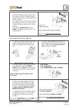
If repair or replacement of the cord or plug is necessary, do not connect the green grounding wire
to either flat blade terminal. The wire with insulation having a green outer surface with or without
yellow stripes is the grounding wire and must be connected to the grounding pin.
Check with a qualified electrician or serviceman if the grounding instructions are not completely
understood, or if you are in doubt as to whether the product is properly grounded. Do not modify
the plug provided. If the plug will not fit the outlet, have the proper outlet installed by a qualified
electrician.
This product is for use on a nominal 220 volt circuit and has a grounding plug that looks like the
plug illustrated below. Make sure that the product is connected to an outlet having the same con-
figuration as the plug.
No adapter should be used with this product.
2. Components and Description
Components
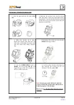
The shipping carton for your painting system contains the following:
Suction tube and return tube
Separating Oil
Spray gun with filter
Spray tip assembly (see chart on next page)
1/4” diameter pressure hose
Instruction manual
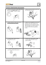
Controls and Functions
ON/OFF Switch
The ON/OFF switch turns the power to the sprayer on and off (O=OFF, l=ON).
Suction tube
Fluid is drawn through the suction tube into the pump.
Fluid Section
A piston in the fluid section moves up and down to create the suction that draws fluid
through the suction tube.
Spray Gun
The spray gun controls the delivery of the fluid being pumped. The gun model you have de-
pends on
your sprayer model
.
Spray Hose
The spray hose connects the gun to the pump.
Return Tube
Fluid is sent back out through the return tube to the original container when PRIME/SPRAY
knob is in
PRIME position.
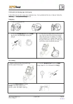
PRIME/SPRAY Knob
The PRIME/SPRAY knob directs fluid to the spray hose when set to SPRAY or the return
tube when set
to PRIME. The arrows on the PRIME/SPRAY knob shows the rotation direc-
tions for PRIME and SPRAY. The PRIME/SPRAY knob is also used to relieve pressure
built up in the spray hose (see
6. Pressure Relief Procedure
).
Pressure Control Dial
The pressure control dial regulates the amount of force the pump uses to push the fluid.
Oiler
The oiler is designed to provide lubrication to the fluid section of the pump.
Pusher stem
The pusher stem is designed to keep the inlet valve open and from sticking due to dried
materials.
https://www.XPOtool.com
Artikel 63003
Seite 7
The Tool Experts
04 2021
-1


