background image


https://www.XPOtool.com 


Item 63027


Page 11


The Tool Experts


01 2022

-1


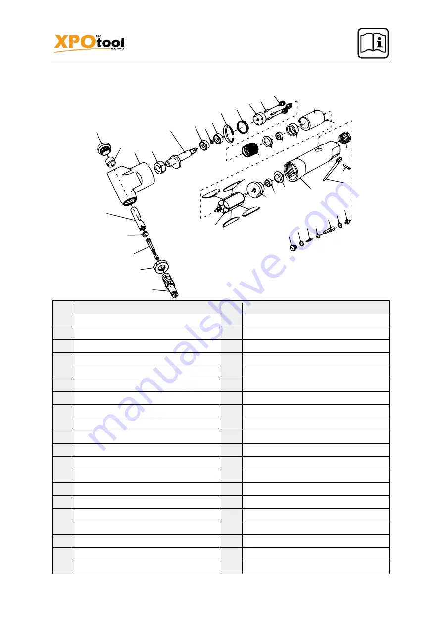
Exploded view and parts list


Name


Name


1


Air inlet bushing


21


Washer


2


Trigger lever


23


Gear case


3


Handle pin


24


Idler gear


4


Handle sleeve


25


Rear spindle


5


O-ring holder


26


Idler gear pin


6


O-ring


27


Nibbler head


7


Valve stem


28


Connecting rod bushing


8


Valve ball


29


Connecting rod


9


Spring


30


Cutter


10


Plug


31


Screw


11


O-ring


32


Die


12


Rear end plate


33


Nut


13


Bearing


34


Drive bushing


14


End plate cap


35


Shaft


15


Rotor


36


Bearing


16


Vane


37


Washer


17


Cylinder


39


Snap ring


18


Pin


40


Nut


19


Front end plate


41


Plug


20


Bearing


Summary of Contents for 63027

Page 1: ...nstructions and safety information before using for the first time Technical changes reserved Due to further developments illustrations functioning steps and technical data can differ insignificantly...

Page 2: ...r contact form https www wiltec de contacts The most recent version of this manual in various languages can be found in our online shop via https www wiltec de docsearch Our postal address is WilTec W...

Page 3: ...se the risk of electric shock fire and injury Do not use the tool in environments with a risk of explosion for example near flammable liquids gases or dust When using the tool sparks can be created wh...

Page 4: ...ol used by inexperienced individuals is dangerous Carefully maintain the tool Keep cutting tools sharp and clean A properly maintained tool with sharp cutting surfaces is less prone to get stuck and t...

Page 5: ...tances To reduce the associated hazards always work in well ventilated areas and wear approved safety equip ment such as a respirator specifically designed to filter out microscopic components Warning...

Page 6: ...ice Schedule times during the day when you will not be exposed to vibrations Hold the tool in your hand as loosely as possible but ensure to always have control over it Let the tool do the work To red...

Page 7: ...SEVERE INJURY DUE TO UNINTENDED START UP Do not install a quick connector with female thread Such a coupling has an air valve through which the compressed air tool can retain pressure which means tha...

Page 8: ...tructions 1 If an automatic oiler is not used add a few drops of pneumatic tool oil to the air line connector before use Add a few more drops after every hour of continuous use 2 Make sure that the sh...

Page 9: ...can cause an explosion Cleaning maintaining lubricating the tool Note The measures described here apply in addition to the regular checks and maintenance proce dures explained as part of normal operat...

Page 10: ...hnician clean and lubricate the mechanism in stall in line air filter see above Vanes worn or damaged Replace all vanes Housing becomes hot during use Incorrect or insufficient lubrica tion Lubricate...

Page 11: ...e sleeve 25 Rear spindle 5 O ring holder 26 Idler gear pin 6 O ring 27 Nibbler head 7 Valve stem 28 Connecting rod bushing 8 Valve ball 29 Connecting rod 9 Spring 30 Cutter 10 Plug 31 Screw 11 O ring...

Page 12: ...eparate col lection system for these appliances The logo on the article or on its packaging points out that this article must not be treated as normal house hold waste but must be disposed to a recycl...

Reviews: