background image


https://www.XPOtool.com 


Item 63368


Page 6 


The Tool Experts


06 2022-1


5.


To position the table, loosen the support lock handle and adjust the table to the desired position. 
Tighten the lock handle again to fix the table in this position.


6.


To tilt the table, loosen the bevel lock screw, position the table in the desired angle on the scale, 
and re-tighten the lock screw.


7.


After drilling a hole, release the feed handle so that the spindle sleeve can return to its original 
position.


8.


If there is any malfunction or abnormal noise during operation, stop the motor immediately and 
investigate the cause.


9.


After finishing work, disconnect the machine from the power supply and remove chips and dirt. 
Apply oil to all unpainted surfaces to protect them from rust.


Operating the laser


Attention! 

Do not look directly into the laser beam. Never point the beam towards a person or an object 

besides the work piece. Never direct the laser beam towards persons or animals. Looking directly into 
the laser beam can lead to flash blindness.


Only operate the machine after it has been mounted completely.


Make sure to observe all electric rules; also make sure that the machine is earthed correctly.


Make adjustments with the device turned off.


The laser radiation used in this laser centring system is of class 2 and has a maximum of 1 mW and 
400–700 nm wavelength. Usually, this kind of lasers are not optically dangerous; however, looking di-
rectly into the beam can lead to flash blindness.


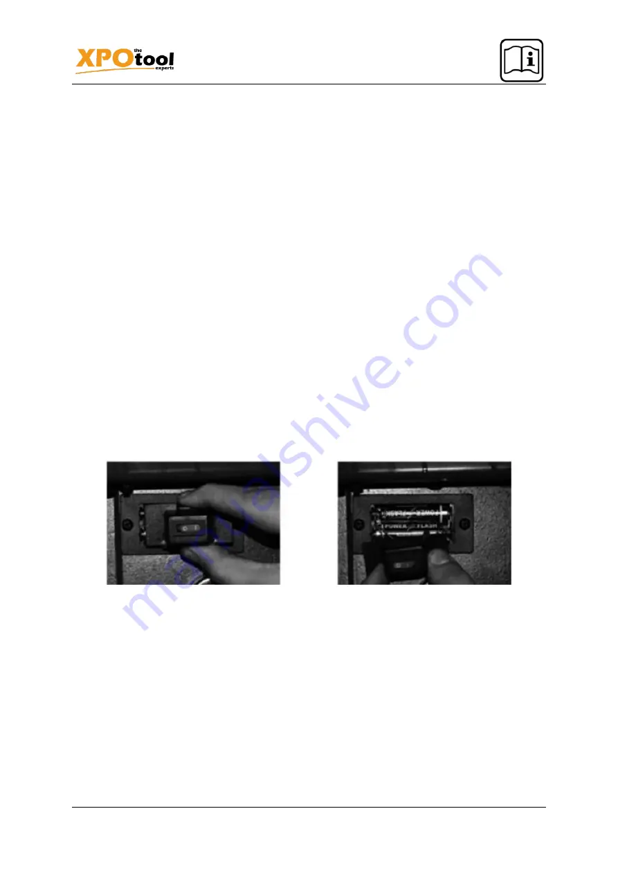
Exchanging the batteries


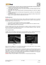
Untighten the lid of the battery compartment to access the batteries (Fig. A). Replace the two AA bat-
teries and make sure to insert the new batteries respecting the correct polarity (Fig. B).


Fig. A


Fig. B


Only use two AA batteries. Do not use old and new  batteries at the same time. Do not use alcaline 
batteries, zinc-carbon battery, or nickel-cadmium batteries.


Re-place the battery lid of the laser and make sure that the laser beam is not directed towards a person’s 
eyes. Always make sure that the laser beam is directed to a stable work piece whose surface does not 
reflect  light,  e.g.,  wood  or  rough  surfaces.  Bright,  shiny,  reflecting,  or  comparable  sheet  steel  is  not 
suitable for use with a laser; the reflecting surface might reflect the beam towards the user. Only switch 
the laser beam on after the work piece has been placed.


Attention!


Remove the laser batteries in case the device is not used during several days.


Summary of Contents for 63368

Page 1: ...ions and safety information before using for the first time Technical changes reserved Illustrations functional steps and technical data may deviate insignificantly due to continuous further developme...

Page 2: ...f you have found an error or wish to suggest an improvement we look forward to hearing from you Send us an e mail to service wiltec info or use our contact form https www wiltec de contacts The most r...

Page 3: ...pproved respiratory mask as dust from certain ma terials may be harmful to your health Make sure that all adjusting tools have been removed from the device Ensure that there are no foreign objects e g...

Page 4: ...bly onto the column 5 Attach the table support lock handle 2 to the table support 1 by inserting it from the left Tighten the connection by hand 6 Clean the tapered hole of the chuck Use a clean cloth...

Page 5: ...hine in order to become familiar with the structure controls and drive system of the machine 2 All ball bearings have been greased at the factory No further lubrication is required Lubricate the groov...

Page 6: ...ve all electric rules also make sure that the machine is earthed correctly Make adjustments with the device turned off The laser radiation used in this laser centring system is of class 2 and has a ma...

Page 7: ...ct between the drill and work piece Re tighten the adjusting screw Attention When adjusted incorrectly the batteries might leak and damage the laser light device Circuit diagram The power supply for t...

Page 8: ...views and parts lists Name Name 1 Rubber bushing 9 Spacer 2 Knob 10 Pulley insert 3 Head pan screw M5 0 8 12 11 Spindle pulley 4 Belt 5 16 26 12 Screw M6 1 12 5 Cover 13 Cord clamp 6 Screw M6 1 0 1 2...

Page 9: ...em 63368 Page 9 The Tool Experts 06 2022 1 Name Name 1 Gasket 7 Spindle shaft 2 Ball bearing 12 mm 8 Chuck 3 Sleeve 9 Chuck key 4 Screw M5 0 8 20 10 Hex nut M6 1 0 5 Stop collar 11 Hex nut M5 0 8 6 Re...

Page 10: ...25 25 20 Screw M5 0 5 12 5 Motor pulley 21 Locking switch 6 Hexagonal head screw M6 1 0 10 22 Self tapping screw 7 Motor 23 Switch cover 8 Motor stop 24 Main switch 9 Motor stop spring 25 Wire connect...

Page 11: ...on and other European countries with a separate waste collection system for these devices The symbol on the packaging or the product itself indi cates that this product must not be treated as normal d...

Reviews: