background image

34

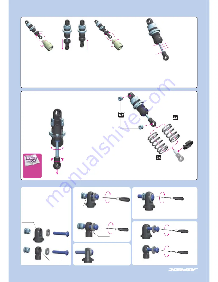
SHOCK ABSORBERS

TECH TIP 

Follow this tech tip to properly install pivot balls 
into the top pivot and bottom ball joint.

Parts Needed:
• M3 x 16 SH screw
• M3 shim

Note that the composite parts have two sides, 
noticeable around the pivot ball hole: one side 
has a shiny fi nish, the other side has a regular 
fi nish.

Install pivot balls into top pivot or 
lower ball joint as shown, on the 
proper sides.

Note that the lower pivot ball has 
an extra shoulder.

Remove screw and shim

SHINY
FINISH SIDE

Ensure pivot balls move freely

SHINY
FINISH SIDE

After the shock is assembled you have to set the Shock Rebound. 

1. To set the Shock Rebound, release the shock composite lower cap.

2. VERY SLOWLY do the following:  Fully pull out the shock rod, push it back in fully, and then fully pull 
it out once more. Repeat this procedure the following number of times to achieve the desired Shock 
Rebound setting:
10 times - approximately 75% rebound (high rebound - suggested for very low traction track)
15 times - approximately 50% rebound (medium rebound - suggested for standard track)
20 times - approximately 25% rebound (low rebound - suggested for very high traction track)

During the Rebound Adjustment procedure shock oil will leak out of the shock body through the O-ring 
on the shock rod... this is normal. During the Rebound Adjustment procedure DO NOT open the upper 
shock cap. 

Cutaway view of 

assembled shock absorber

HARDEST

SOFTEST

1

2

3

4

FRONT SHOCKS
(SHORTER SPRINGS)

CHECK NEXT 

TECH TIP

REAR SHOCKS
(LONGER SPRINGS)

Shock length adjustment:

It is VERY important that all shocks are equal length.
Fully extend the shock absorber and measure the end-to-end 
length; we recommend using digital calipers to give an accurate 
measurement. If a shock absorber is shorter or longer than others, 
adjust the shock length by tightening or loosening the ball joint on 
the shock rod.

Damping adjustment:

If you built the adjustable shocks, fully extend the shock rod and turn it 
slightly to lock the piston in the shock body. 

Turning the shock rod fully CCW aligns 4 holes in the pistons (softest 
damping). Turning the shock rod fully CW aligns 1 hole in the 
pistons (hardest damping). The shocks have four settings, each of 
which can be felt by a slight "click". 

Set all four shocks initially to position 3 (3 holes open): turn fully 
CCW, then turn CW by 1 click.

RELEASE

TIGHTEN

3. After you have set the Rebound Adjustment, re-install the shock lower composite cap.

4. Check the Shock Rebound setting by pushing the shock rod fully into the shock body, releasing it, and 
observing how far the shock rod extends by itself:
* 25% out of the shock body (low rebound)
* 50% out of the shock body (medium rebound)
* 75% out of the shock body (high rebound).
If the shock rod rebounds too much, return to Step 1 and repeat the procedure.

If the shock rod does not rebound enough, you will have to refill the shock with shock oil, and then repeat 
the bleeding and Shock Rebound procedure.

0%

50%

REBOUND

75%

REBOUND ADJUSTMENT

REBOUND CHECK

SHOCK DAMPING 

ADJUSTMENT

SPRING RATE SELECTION

Tighten screw until pivot ball 
snaps into place

SHINY
FINISH SIDE

SHINY
FINISH SIDE

100%

25%

Summary of Contents for NT1

Page 1: ......

Page 2: ...low instructions supplied with paints and or cement if used not included in kit Immediately after using your model do NOT touch equipment on the model such as the motor and speed controller because th...

Page 3: ...e right to make the nal determination of the warranty status of any component or part Limitations of Liability XRAY makes no other warranties expressed or implied XRAY shall not be liable for any loss...

Page 4: ...Shockabsorber Assembly Tool HUDY 183010 Phillips 3 5mm Allen Ball 2 5mm Socket 7 0mm Allen 3 0 2 5 2 0 1 5mm Pinion Tools HUDY 182001 182002 Flywheel Tool HUDY 182010 Pliers Scissors Side Cutters Hob...

Page 5: ...0 3206 HEX SCREW SFH M2x6 10 90 3258 HEX SCREW SFH M2 5x8 10 96 2051 WASHER S 5x10x0 2 10 96 4031 WASHER S 3 5x10x0 2 10 96 4050 WASHER S 5x15x0 3 10 97 1240 SILICONE O RING 24x0 7 10 97 2050 SILICONE...

Page 6: ...SFH M2 5x8 964031 S 3 5x10x0 2 Fill differential up to the top of the diff pins DO NOT ll the diff to the top of the housing Remove the nozzle of the bottle to allow easy lling of the diff Tighten th...

Page 7: ...0 3258 HEX SCREW SFH M2 5x8 10 96 2051 WASHER S 5x10x0 2 10 96 4031 WASHER S 3 5x10x0 2 10 96 4050 WASHER S 5x15x0 3 10 97 1240 SILICONE O RING 24x0 7 10 97 2050 SILICONE O RING 5x2 10 98 1210 PIN 2x1...

Page 8: ...this order After disassembling the differential the large O ring may have an increased size and may be more dif cult to re install We recommend either replacing the O ring or carefully inserting the...

Page 9: ...ANTI ROLL BAR BALL JOINT 5 8 MM 4 33 4040 BRAKE CAM POST ALU 7075 T6 33 4050 COMPOSITE BRAKE UPPER PLATE COMPOSITE CLAMPS 33 4110 VENTILATED BRAKE DISK LASER CUT PRECISION GROUND 33 4120 HARDENED STEE...

Page 10: ...6mm 2 5mm COMPLETED ASSEMBLY REAR ARMS LEFT REAR ARM RIGHT REAR ARM LEFT REAR ARM RIGHT REAR ARM 0 5mm 0 5mm Use 0 5mm suspension holders for initial assembly REAR ROLL CENTER INSERT POSITIONS 1 5mm 0...

Page 11: ...Both bushings must be in same position INITIAL POSITION Place tab in this notch A B REAR BELT TENSION ADJUSTMENT TO TIGHTEN REAR BELT Rotate BOTH rear composite bushings in arrow direction A TO LOOSE...

Page 12: ...that the composite ball joints have two sides noticeable around the pivot ball hole one side has a shiny nish the other side has a regular nish Install pivot ball into ball joint from the SHINY side...

Page 13: ...ls must move freely During initial assembly tighten each aluminum hex nut until the pivot ball starts to bind then loosen slightly Verify that the pivot balls move freely Tighten aluminum hex nuts usi...

Page 14: ...902306 SH M3x6 ALU SHIM 1MM ALU SHIM 2MM INITIAL POSITION 47mm Follow the TECH TIP on page 13 to install the pivot balls 6 m m INITIAL POSITION 3 2mm 3mm INITIAL SETUP NOTE THE 90 ANGLE DIFFERENCE BE...

Page 15: ...ING STEEL 33 5800 COMPOSITE BELT PULLEY COVER SET 33 5828 COMPOSITE BELT PULLEY 18T 2 SPEED SIDE 90 1305 HEX SCREW SB M3x5 10 90 3306 HEX SCREW SFH M3x6 10 90 8262 HEX SCREW SOCKET HEAD CAP M2 5x12 10...

Page 16: ...e Top of screw head should be level with hole bottom edge ASSEMBLED VIEW NOTE ORIENTATION 59 54 NOTE ORIENTATION 59 54 Do not overtighten gap setting setscrews Only tighten until roller pins contact t...

Page 17: ...5255 COMPOSITE WHEEL HUB 2 33 5430 PUR REINFORCED DRIVE BELT FRONT 3 x 186 MM 33 7210 FRONT LOWER INNER PIVOT PIN 2 33 7220 FRONT UPPER PIVOT PIN 2 33 7250 STEEL PIVOT BALL 8 4 MM 2 33 7252 ALU ADJUS...

Page 18: ...FRONT BELT TENSION ADJUSMENT TO TIGHTEN FRONT BELT Rotate BOTH front composite bushings in arrow direction A TO LOOSEN FRONT BELT Rotate BOTH front composite bushings in arrow direction B 1mm 0 5mm 1...

Page 19: ...the pivot ball starts to bind then loosen slightly Verify that the pivot balls move freely STEERING BLOCK STEERING BLOCK STEERING BLOCK Ensure that the front suspension moves freely DETAIL WHEEL AXLE...

Page 20: ...1 33 6250 COMPOSITE BATTERY MOUNT L R 2 90 2308 HEX SCREW SH M3x8 10 90 2312 HEX SCREW SH M3x12 10 90 3308 HEX SCREW SFH M3x8 10 94 0613 HIGH SPEED BALL BEARING 6x13x5 RUBBER SEALED 2 95 0510 BALL BE...

Page 21: ...H M3x12 950510 BB 5x10x4 NOTE ORIENTATION ASSEMBLED VIEW NOTE ORIENTATION NOTE ORIENTATION NOTE ORIENTATION Release upper screw Move belt tensioner as needed Re tighten upper screw DETAIL Use the belt...

Page 22: ...MM HEX 4 90 2308 HEX SCREW SH M3x8 10 90 2310 HEX SCREW SH M3x10 10 90 3308 HEX SCREW SFH M3x8 10 94 0508 HIGH SPEED BALL BEARING 5x8x2 5 RUBBER SEALED 2 97 0100 O RING 10 x 1 5 10 333240 940508 3325...

Page 23: ...install the pivot balls There are two different Ackermann inserts labeled AD and CB You can insert each of the Ackermann inserts in two different orientations which will result in the different Ackerm...

Page 24: ...ADIO PLATE 33 6120 COMPOSITE STEERING SERVO HOLDER SET 33 6150 COMPOSITE BATTERY PLATE 33 6190 COMPOSITE ROLL OVER BAR 33 6200 STEERING SERVO ARMS SET 33 8600 FUEL TANK 75CC SET 33 8685 FUEL TANK MOUN...

Page 25: ...se appropriate shims to ensure there is at least 1mm clearance between the servo horn and the front middle shaft 1 5mm 1mm NOTE ORIENTATION B A A thin thick Use different servo shims depending on your...

Page 26: ...Use tape to mount the receiver battery pack to the lower holder Antenna 3x8 3x8 2x6 DETAIL Servo arm must be perpendicular to linkage when servo is in neutral 90 95 Personal Transponder not included R...

Page 27: ...5 9050 CLUTCH BELL BALL BEARING MR105ZZ 5x10x4 2 90 1406 HEX SCREW SB M4x6 10 90 2408 HEX SCREW SH M4x8 10 90 3310 HEX SCREW SFH M3x10 10 90 8310 HEX SCREW SOCKET HEAD CAP M3x10 10 90 8316 HEX SCREW S...

Page 28: ...ect gap Thickness of shims required in mm A B 0 7 Apply shims on crankshaft to set endplay to 0 05 0 15mm 1 ADJUSTING THE CLUTCH GAP ENDPLAY SHIMS CLUTCH GAP SHIMS These shim are used to adjust clutch...

Page 29: ...mounts as follows STEP 1 Attach lower mounts to chassis STEP 2 Attach upper mounts to lower mounts STEP 3 Attach engine to upper mounts STEP 4 Loosen lower mount screws adjust gear mesh and then retig...

Page 30: ...6 10 90 2308 HEX SCREW SH M3x8 10 90 2310 HEX SCREW SH M3x10 10 90 2312 HEX SCREW SH M3x12 10 90 3308 HEX SCREW SFH M3x8 10 90 3310 HEX SCREW SFH M3x10 10 96 0030 NUT M3 10 98 1212 PIN 2x12 10 902306...

Page 31: ...3x6 Screw from servo INITIAL POSITION INITIAL POSITION Insert rod through hole in brake arm Bend rod to proper shape ASSEMBLED VIEW CARB LINKAGE BODYMOUNTS NOTE DIFFERENT TYPES OF SCREWS Approx 15mm K...

Page 32: ...FOAM INSERTS 4 30 8301 XRAY SHOCK ABSORBER SET 4 STEP 2 30 8316 T2 SHOCK BALL JOINT OPEN 4 30 8330 T2 COMPOSITE FRAME SHOCK PARTS 4 STEP 30 8351 T2 SHOCK CAP NUT ALU 2 30 8361 T2 HARDENED SHOCK SHAFT...

Page 33: ...the shock body with shock oil Let the oil settle and allow air bubbles to rise to the top Slowly move the piston up and down until no more air bubbles appear Add shock oil as necessary Pull the pisto...

Page 34: ...XT TECH TIP REAR SHOCKS LONGER SPRINGS Shock length adjustment It is VERY important that all shocks are equal length Fully extend the shock absorber and measure the end to end length we recommend usin...

Page 35: ...IP FOR 6MM BODY POST 4 33 9800 FRONT WHEELS STARBURST WHITE 2 33 9801 REAR WHEELS STARBURST WHITE 2 90 2306 HEX SCREW SH M3x6 10 96 0240 NUT M4 WITH SERRATED FLANGE 10 INITIAL POSITION 309402 FINAL AS...

Page 36: ...IAL POSITION 902306 SH M3x6 960240 N M4 REAR SHOCKS LONGER SPRINGS REAR TIRES WIDE FRONT TIRES NARROW TIRES NOT INCLUDED Cut 2 pieces of silicone tubing and install as follows pressure line between ex...

Page 37: ...throttle control e g throttle trigger is at 95 of full throttle The servo should not have excessive strain when at full throttle or throttle carb damage will result If the transmitter does not have th...

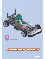
Page 38: ...38 FINAL ASSEMBLY VIEW PLEASE REFER TO THE NT1 SET UP BOOK FOR INFORMATION ABOUT PROPER SETUP OF YOUR NT1...

Page 39: ...TURER NO DIAMETER mm 5 MIN WEAR mm RUBBER TIRES INSERT SHORE deg TIRES REAR FRONT ANTI ROLL BAR ENGINE CLUTCH BRAKE BODY DIFF 0 30 45 60 90 mm mm RIGHT LEFT RIGHT LEFT STANDARD STANDARD CLUTCH FLYWEIG...

Page 40: ...C AMERICA 167 TURTLE CREEK BLVD SUITE C DALLAS 752 07 TEXAS USA PHONE 214 744 2400 FAX 214 744 2401 xray rcamerica com RC AMERICA 167 TURTLE CREEK BLVD SUITE C DALLAS 752 07 TEXAS USA PHONE 214 744 24...

Reviews: