8
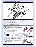
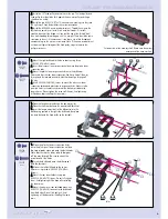
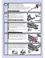
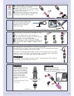
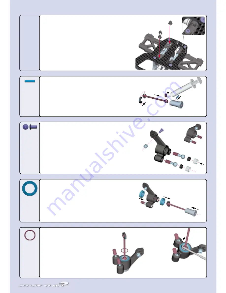
Remove any excess plastic flash from the holes in the uprights before beginning assembly.
1
1..
Insert a #30 7350 pivot ball through each of the pivot holes in the # 30 3310 rear
uprights.
2
2..
Place the plastic ball cups on top of the pivot balls. The concave (scooped) side goes
against the pivot balls.
3
3..
Thread the plugs into the tapped holes atop the pivot balls and ball cups. Adjust the
plugs so the pivot balls have the least amount of play while still allowing free movement in
the uprights.
4
4..
Thread a #30 9333 (SH M3x6) screw through one of the upper holes on the upright,
and into a #30 3240 pivot ball. Tighten the screw into the pivot ball until you feel a "snap".
RReeppeeaatt ffoorr bbootthh ssiiddeess,, bbuutt iinn sstteepp 4
4,, tthhee ssccrreew
w sshhoouulldd ggoo tthhrroouugghh tthhee ooppppoossiittee ssiiddee ooff tthhee
uupprriigghhtt..
1
1..
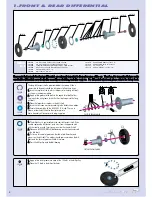
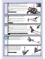
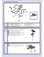
Slide a #309054 (BB 10x15) ball-bearing onto the wheel axle.
2
2..
Insert the drive shaft through the upright until the bearing on the axle is seated.
Note the direction of installation from the diagram.
3
3..
Slide another #309054 (BB 10x15) bearing over the drive shaft. Press the
bearing into the upright, making sure that it fits precisely.
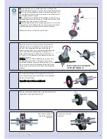
1
1..
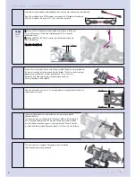
Lightly grease a #30 5230 coupling and insert it into the drive shaft joint.
2
2..
Slide the drive shaft joint into #30 5310 the wheel axle, aligning the
holes.
3
3..
Insert the #30 9452 (P 2x10) cross pin through the aligned holes in the
coupling and wheel axle. Make sure it is evenly spaced on both sides of the
wheel axle.
4
4..
Install the plastic cap onto the drive shaft pin. First insert one hole of the
plastic cap over a pin, then stretch the other hole over the other pin.
RReeppeeaatt ffoorr bbootthh aaxxlleess..
1
1..
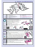
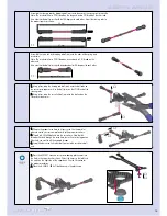
Release the pivot pin set screw to allow the arm to slide back and forth on the pin, so
you can install the wheelbase clips on the pivot pin.
2
2..
Install the #30 2080 wheelbase clips. Use only three clips (one each of 4mm, 3mm,
and 2mm) on each arm. The initial setting is to install two clips (3 mm and 2 mm) in
front of the arm, and one 4 mm clip behind the arm. For adjustment, refer to the Set-Up
Book.
Note: If you find that the arm does not move freely after installing the clips, remove the
4mm clip, lightly sand one side, and reinstall. Repeat this until the arm moves freely with
all three clips installed.
3
3..
Tighten the pivot pin set screws very lightly. Be careful not to overtighten them.
RReecchheecckk tthhee aarrm
mss ffoorr ffrreeee m
moovveem
meenntt..
Fasten the axle to the upright by installing a snap ring in
the groove in the wheel axle (near the drive shaft joint). To
make installation easier, place the hex portion of the wheel
axle flat on a table. Put one end of the snap ring into the
groove on the opposite side of the axle cutout, and use a
slotted screwdriver to work the rest of the clip into the
groove.
RReeppeeaatt ffoorr tthhee ootthheerr aaxxllee aanndd uupprriigghhtt..
➊
➋
➌
➍
➊
➋
➌
➍
➍
➊
➋
➌
REAR SUSPENSION
309452
P 2x10
309333
SH M3x6
309054
BB 10x15
309425
C 10
To remove the snap ring, insert a small
screwdriver in the axle cutout and pry it off,
taking care not to let it fly off the workbench.
LEFT
RIGHT
G
GR
REE
A
ASS
EE
4mm
3mm
2mm
Summary of Contents for T1 EVO2
Page 1: ......


