background image


6   

Rev. 1.0 31/01/2020 


EN 


Safety information 


Definitions of warning words and symbols 

This manual contains extremely important safety information, in order to avoid personal injury, damage to 

the instrument, malfunctions or incorrect results due to failure to comply with them. Read entirely and 

carefully this manual and be sure to familiarize with the tool before starting to work with it. 
This manual must be kept near to the instrument, so that the operator can consult it easily, if necessary. 
Safety provisions are indicated with warning terms or symbols. 


Reporting terms: 

ATTENTION

   for a medium-risk hazardous situation, which could lead to serious injury or death, if 

not avoided. 


ATTENTION

     for a dangerous situation with reduced risk which can cause material damage, data loss 

or minor or medium-sized accidents, if not avoided. 


WARNING

         for important information about the product 


NOTE

                for useful information about the product 


Warning symbols: 


Attention 

This symbol indicates a potential risk and warns you to proceed with 

caution. 


Attention 

The instrument must be used following the indications of the reference 

manual. Read the instructions carefully. 


Warning 

This symbol draws the attention to possible damage to the instrument 

or instrumental parts. 


Note 

This symbol highlights further information and tips. 


Attention 

This symbol draws  the  attention to a possible danger 

from electric 

current

.


Summary of Contents for 60 VioLab Series

Page 1: ...1 Rev 1 0 31 01 2020 EN 60 VioLab INSTRUCTIONS MANUAL pH Cond PC ...

Page 2: ...2 Rev 1 0 31 01 2020 EN ...

Page 3: ...ion 10 Display 10 Keyboard 10 LED 11 Installation 11 Supplied components 11 Start Up 11 Connection of the power supply 11 Power on date and time update power off 12 Instrument transportation 12 Key functions 13 Inputs Outputs Connections 13 Symbols and icons on the display 14 Operation of the device 15 Setup menu 16 Setup Menu Structure 17 Temperature measurement ATC MTC 18 pH Parameter 18 pH para...

Page 4: ...ed out with the Conductivity cell 34 TDS Parameter 34 Salinity 34 Data Logger Function 35 Setup for Data Logger parameter 35 Composition of setup menu for the Data Logger menu 36 Example of automatic Data Logger mode 37 Example of manual Data Logger mode 37 Example of printing a value 37 Recall Memory 38 Clear the saved data 38 Instrument Setup Menu 38 Composition of the setup menu for Setting Men...

Page 5: ...d step by step and the instrument configuration menu is easy to consult In addition a LED indicates the status of the system to the user Up to 3 pH calibration points can be carried out between 10 automatically recognized values and 5 points for Conductivity in addition buffers chosen by the operator can be used It is also possible to perform mV calibration for Redox sensors For an accurate measur...

Page 6: ...risk hazardous situation which could lead to serious injury or death if not avoided ATTENTION for a dangerous situation with reduced risk which can cause material damage data loss or minor or medium sized accidents if not avoided WARNING for important information about the product NOTE for useful information about the product Warning symbols Attention This symbol indicates a potential risk and war...

Page 7: ...safety are guaranteed only if all the following indications are respected the instrument can be used in accordance with the specifications mentioned above only use the supplied power supply only If you need to replace the power supply contact your local distributor the instrument must operate exclusively in the environmental conditions indicated in this manual no part of the instrument can be open...

Page 8: ...rous for the user himself For the maintenance of the electrochemical sensors refer to the documentation present in their packaging or contact the supplier Responsibility of the owner of the instrument The person who owns and uses the tool or authorizes its use by other people is the owner of the tool and is responsible for the safety of all users of the tool and third parties The owner of the inst...

Page 9: ...1 user value Reference temperature 15 30 C Temperature coefficient 0 00 10 00 C TDS COND 60 VioLab PC 60 VioLab Measuring range TDS Factor 0 1mg l 200 gr l 0 40 1 00 Salinity COND 60 VioLab PC 60 VioLab Measuring range 0 1ppm 100ppt Temperature pH 60 VioLab COND 60 VioLab PC 60 VioLab Measuring range 10 110 C Resolution Accuracy 0 1 0 5 C Temperature compensation ATC NTC30KΩ and MTC 0 100 C System...

Page 10: ...p from the measure mode Measurement parameter Indication of instrumental mode Representation of buffers used for calibration Error symbol Actual value Measure unit Temperature and type of compensation ATC automatic NTC 30KΩ MTC manual Information icons on connectivity and Data Logger Progressive number of data saved in Data Logger mode Stability indicator Text string Date and time Battery charge l...

Page 11: ...ns in single dose bottle and or sachet electrode holder stand multilingual user manual and test report There are versions with the sensor s already included Contact your local distributor to be updated on the correct composition of the sales kit Start Up Place the instrument on a flat stable laboratory table with appropriate front and side accessibility It is recommended to place the instrument at...

Page 12: ...confirm with the key Carry out the same operation with the month and day and subsequently with hours and minutes The instrument will enter measure mode in the last parameter used To switch off the instrument press the key in measure mode Instrument transportation To move the instrument to a new location ship it carefully to avoid damage the instrument can be damaged if it is not transported correc...

Page 13: ...d customer calibration mode press to change the value In measure mode press to save the data or print In measure mode press to recall the saved data Long Press 3s In measure mode keep one of the two keys pressed to change the temperature in MTC mode manual compensation without probe When the value starts to flash the user can change the temperature value by entering the correct one and confirming ...

Page 14: ...g FIXED Calibration deadline set for that parameter INTERMITTENT Calibration deadline active for that parameter Press the directional keys to change the parameter or value on the display DHS digital sensor connected The bars scroll if the measurement is not stable Measurement stability indicator 4mm banana for reference electrode BNC for pH and ORP electrodes RCA for pH temperature probe RCA for C...

Page 15: ...ioLab pH Conductivity pH mV TDS mV ORP Salinity ORP Conductivity TDS Salinity Note Pressing the button after the last parameter the instrument automatically restarts from the first one In the measurement screens for the pH ORP and Conductivity parameters press the key to start the calibration of the active parameter next paragraphs On the left side of the display through a string of different colo...

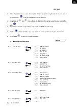
Page 16: ...nstrument The instrument is in the Recall Memory mode The data that have been stored are being displayed by running the manual or automatic Data Logger Setup menu In measure mode press the key to enter SETUP mode select the parameter you want to edit by using the directional keys and confirming with pH 60 VioLab COND 60 VioLab PC 60 VioLab pH SETTINGS COND SETTINGS pH SETTINGS ORP SETTINGS TDS SET...

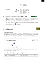
Page 17: ...editable using the directional keys Press the key to return to the previous menu Setup Menu Structure P1 0 pH SETTINGS P1 1 Buffer Selection P1 2 Resolution P1 3 Set Stability P1 6 View pH Cal P1 7 Due pH Cal P1 8 Reset pH Setting P1 9 Temp Cal pH P2 0 ORP SETTINGS P2 6 View ORP Cal P2 7 Due ORP Cal P2 8 Reset ORP Setting P2 9 Temp Cal ORP P3 0 COND SETTINGS P3 1 Cell Constant P3 2 Buffer Selectio...

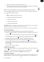
Page 18: ...H sensors with integrated temperature probe or to connect two different sensors Connect the pH electrode to the BNC type connector marked in green Connect the temperature probe to the RCA CINCH Temp connector always marked with a green background The instrument is also able to recognize the DHS sensor an innovative electrode that stores calibration data and that can be used immediately after on an...

Page 19: ...he last automatic and manual calibration was carried out P1 2 Resolution Access this menu to choose the resolution needed when reading the pH parameter 0 1 0 01 default P1 3 Stability criteria in pH measurement To consider the reading of a value truthful we recommend waiting for the measurement stability indicated by the icon When the measurement is not stable four red flashing bands appear on the...

Page 20: ... GLP protocols By default no calibration deadline is set Use the directional keys to select HOURS or DAYS and access with button Use the directional keys to change the number that appears in the center of the display entering the hours or days that must elapse between two settings and confirm with If a calibration deadline is set the icon is present on the display in measure mode When the calibrat...

Page 21: ...t is now ready to recognize the second calibration point Next to the string 2ND POINT PH the different buffers that the device can recognize automatically scroll When the 4 01 value is recognized and the icon appears press the key as indicated by the string PRESS OK The actual measured value and the Slope flash on the display subsequently the icon of the beaker pH 4 01 appears next to the green be...

Page 22: ...on appears and the value flashes modify it using the directional keys by entering the correct one e g pH 6 79 as suggested by the string ADJUST THE VALUE and by the icon Note Check the buffer value according to the temperature When the icon appears again press the key to confirm the first point the actual measured value flashes on the display and the beaker icon appears with the buffer identificat...

Page 23: ...the appropriate storage solution Never store the sensors in ANY TYPE of water OR DRY It is a useful tool for obtaining accurate measurements always having on the display the indication of the buffers used for calibration and the possibility of consulting the calibration data at any time or entering the expiry date Sensors with DHS technology The electrodes equipped with DHS technology can save a c...

Page 24: ...sor calibration line is out of the acceptable range 80 120 CALIBRATION TOO LONG the calibration exceeded the time limit only the points calibrated up to that moment will be kept mV Parameter pH 60 VioLab PC 60 VioLab In measure mode press the key and move to the mV parameter indicated by the icon The display shows the measurement in mV of the pH sensor The scrolling on the display of four red band...

Page 25: ...VIEW or print select PRINT information on the last calibration performed VIEW The following screens will scroll automatically on the display First screen CALIBRATION DATE and TIME Second screen OFFSET value of the electrode expressed in mV Third screen TEMPERATURE at which the calibration was performed PRINT The following information are printed Model and Serial Number of the instrument Calibratio...

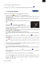
Page 26: ... the instruments in this series are pre calibrated for a correct temperature reading However if a difference between the measured and the real one is evident usually due to a probe malfunction it is possible to perform an offset adjustment of 5 C Use the keys and to correct the temperature offset value and confirm with ORP automatic calibration Automatic calibration with 475 mV solution In ORP mea...

Page 27: ...posite charge poles The reading depends on the geometry of the measuring cell which is described through the constant cell parameter C d A expressed in cm 1 where d represents the distance between the two electrodes in cm and A their surface in cm2 The conductance is transformed into specific conductivity k which is independent of the cell configuration multiplying it by the cell constant k G x C ...

Page 28: ...ion of the standards for performing the calibration AUTOMATIC default The device automatically recognizes up to 3 of the following standards 84 µS cm 147 µS cm 1413 µS cm 12 88 mS cm e 111 8 mS cm CUSTOM the device can be calibrated on a point with a manually entered value Note To obtain accurate results it is advisable to calibrate the device with standards close to the theoretical value of the s...

Page 29: ...fault 1 91 C is set which is suitable for most of the analyses Press the key the value flashes and as indicated by the icon use the directional keys to enter the new coefficient Confirm with key Compensation coefficients for special solutions and for groups of substances are shown in the following table Compensation coefficients for calibration standards at different temperatures for Tref 25 C are...

Page 30: ...nt Calibration Date and time Measuring Range with relative cell constant applied IMPORTANT Make sure that the printer is connected and turned on and that the paper roll and cartridge are correctly positioned For more information refer to the printer user manual NOTE Use the original printer specified by the manufacturer only For information contact your local distributor P3 7 COND Calibration expi...

Page 31: ...cognize alternate The string WAIT FOR STABILITY and the flowing red bands indicate that the measurement is not stable yet When the value stops on 1413 and the icon appears confirm the calibration pressing as indicated by the string PRESS OK The actual measured value flashes on the display and then it is shown the updated cell constant The icon appears which indicates that the instrument is calibra...

Page 32: ...onstant Access the Setup menu for COND SETTINGS and select in the P3 1 0 1 and into the program P3 2 Custom then go back to the measurement and go into COND mode Press the key to enter the calibration mode Rinse the cell with distilled water and dab gently with paper towel Apply few ml of standard solution and immerse the sensor in the conductivity standard 5 00 µS cm The string WAIT FOR STABILITY...

Page 33: ...o scroll through the different screens of parameters until activating the Conductivity parameter indicated by the icon Connect the Conductivity cell to the BNC for Cond of the instrument grey If the user does not use a cell with a built in temperature probe or an external probe NTC 30KΩ it is recommended to manually update the temperature value MTC Remove the cell from its test tube rinse with dis...

Page 34: ...ETUP menu Use the directional keys to move to TDS SETTINGS P4 0 and access the menu by pressing the key Press again to enter the program TDS FACTOR P4 1 When the value flashes use the directional keys as indicated by the icon to enter the correct value and confirm with By default the TDS factor is set at 0 71 the user can change it between 0 40 1 00 Here below the TDS factors in relation to the Co...

Page 35: ...HOURS MINUTES PC Connection connect the USB cable inside each package to the USB port on the top panel of the instrument and the other end to a COM port on the computer Use the USB cable supplied with the instrument only Data Logger on external printer Purchase the printer separately connect it with RS232 cable to the connector identified with Printer on the rear panel of the instrument connect th...

Page 36: ...on the display When it is set but not in operation the icon on the screen remains fixed When the 1000 total values are reached the recording stops automatically Note Scrolling through the parameters the recording stops P8 2 Memory emptying Access this menu and select YES to clear the saved data and empty the memory Next to the M icon It shows the total number of data stored P8 3 Saving destination...

Page 37: ... The icon is lit in the lower string of the display which indicates that an automatic frequency Data Logger has been set Press to start recording the icon starts flashing indicating that the storage is in progress The number next to the M icon indicates how much data has been saved for that parameter Press again to end the recording Note automatic recording is suspended when the measurement parame...

Page 38: ...ot Press to return to measure mode Clear the saved data To clear the data stored in the instrumental memory access the CLEAR DATA P8 2 setup menu and select YES IMPORTANT Factory reset of the pH ORP and Cond parameters does not delete the stored data Instrument Setup Menu In measure mode press key to access the SETUP menu Use the directional keys to move to SETTINGS P9 0 and access the menu by pre...

Page 39: ...up menu it is possible to select which parameters do NOT display in measure mode Access menu P9 6 The icon flashes with directional keys choose YES in measure mode the pH parameter is kept active NO in measure mode the pH parameter is not displayed Confirm the selection with key now the icon flashes then repeat the same operation for the mV parameter and then for all the parameters up to TDS Examp...

Page 40: ... Download the data saved in the instrumental memory are downloaded to a PC and displayed in the table for processing M instantaneous acquisition of a value equivalent to the manual Data Logger option Logger automatic acquisition with set frequency Empty emptying the data in the table If the password is active it will be requested Export to Excel Export to PDF export to PDF and Excel of all the dat...

Page 41: ...cturer will repair or replace defective components This warranty does not apply if the product has been damaged used incorrectly exposed to radiation or corrosive substances if foreign materials have penetrated inside the product or if changes have been made which have not been authorized by the manufacturer Disposal of electrical devices This equipment is subject to the regulations for electronic...

Reviews: