background image

DP200 Page 16 

Crossover modes 

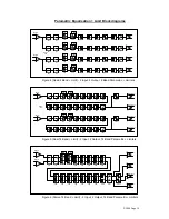
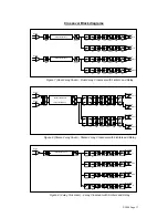
Four crossover modes are provided :- 

2 way dual, 2 way stereo, 4 way mono and 3 way + Sub ‘Split’. Note: 2 way stereo 
mode is identical to 2 way dual but with 'ganged' adjustment of parameters. Please 
see block diagram. All crossover modes feature adjustable crossover frequencies 
with a choice of slopes,  2 bands of driver compensation e.q. per output and delay 
time plus limiters for each output.  A powerful 6 band parametric equaliser is also 
provided on each input for room equalisation. Phase reverse is provided for each 
output. 

Filter slopes 

A choice of Bessel or Butterworth slopes at 12/18/24dB per octave and Linkwitz-
Riley at 24dB per octave are provided. Since Low and High pass functions are 
separately adjusted, asymmetric slopes are easily achieved if required. It should 
also be noted that the turnover frequency displayed on the DP200 is the -3dB point 
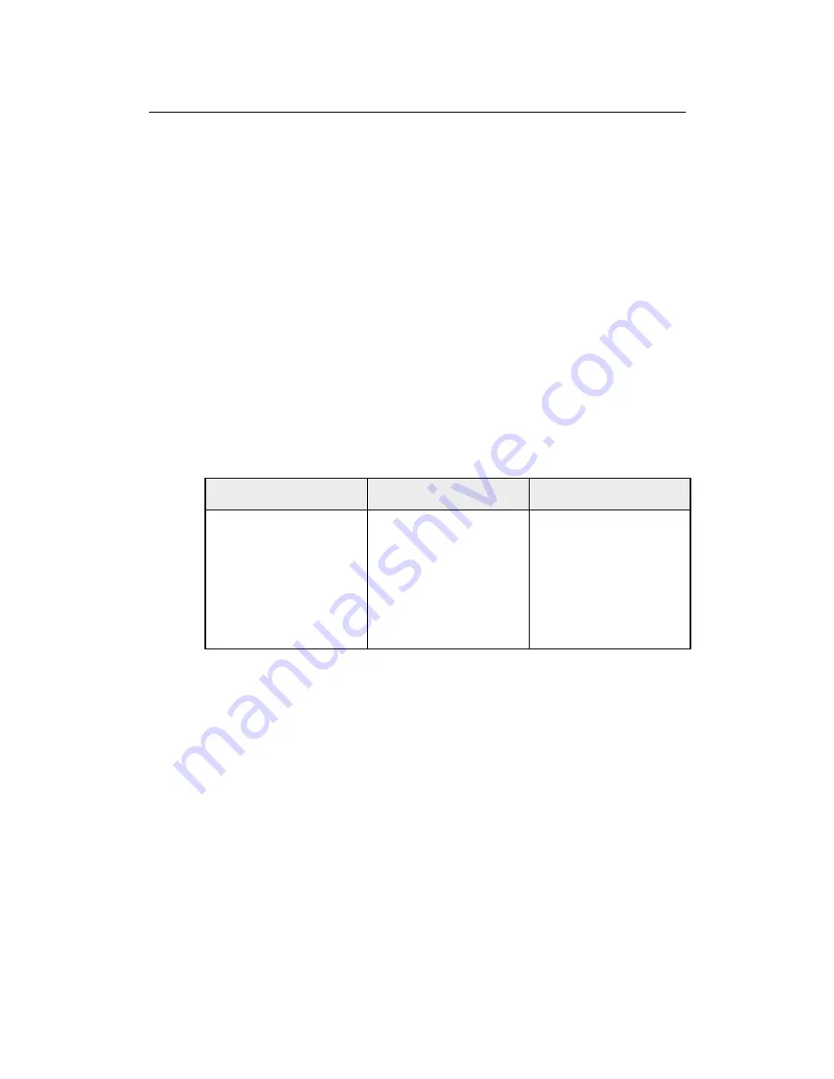
for all slopes except 24dB Linkwitz-Riley where the -6dB point is shown. If the -6dB 
point is to be used for the Bessel or Butterworth filter, take the required crossover 
frequency, multiply this by the appropriate factor from the following table and then 
select the closest available frequency on the DP200's display. 


Filter Type 

High pass filter factors 

Low pass filter factors 

Bessel 12dB/octave 

1.45 

0.69 

Butterworth 12dB/octave 

1.31 

0.76 

Bessel 18dB/octave 

1.37 

0.73 

Butterworth 18dB/octave 

1.19 

0.84 

Bessel 24dB/octave 

1.35 

0.74 

Butterworth 24dB/octave 

1.15 

0.87 

Please note that unlike conventional analogue crossovers, crossover points and 
slopes are set with absolute accuracy since component tolerance problems do not 
occur. 

Time Alignment 

A further advantage of the DP200 over conventional products is the provision of an 
independently adjustable delay section for each output. This allows the true arrival 
time from multiple drivers to precisely aligned rather than relying on the compromise 
'phase adjust' approach.  Delay time is adjustable in 21 micro-second steps (8mm). 
To convert from units of time (i.e. milliseconds) to units of distance use the following 
formula : - 

1 millisecond = 343mm (1.126ft)  @ 20

°

C (68

°

F)  

Output Limiters 

High performance digital limiters are provided for each output with control over 
attack time, release time and threshold level parameters ( see page 22 ). This level 
of control allows the user to balance the required subjective quality of the limiter 
against the driver protection requirements.  It does also mean that an incorrectly set 
limiter may sound awful! In particular, as with all limiters, using too fast an attack or  

Summary of Contents for dp200

Page 1: ......

Page 2: ......

Page 3: ...ossover modes 16 Crossover Block diagrams 17 Gain Delay and Phase Function Screen 19 High and Lowpass Filters Function Screen 20 Parametric Equalisation Function Screen 21 Limiter Control Function Scr...

Page 4: ......

Page 5: ...the following information which is provided for your safety Do not expose this unit to rain or moisture Do not expose this unit to excessive heat Replace all fuses with the correct type only Do not re...

Page 6: ...s 40 bit internal data path for exceptional dynamic range and sonic quality A flexible 2 input 4 output multi mode format featuring a choice of 2 way 4 way 3 way Sub Crossover dual 16 quad 8 band para...

Page 7: ...ovides exceptional audio quality with a full 103dB dynamic range high sampling rate and minimal filtering Wide range digital control of level is provided for each output This also allows mute to be ap...

Page 8: ...function returning the unit to the basic default operating mode from the existing menu selection 5 Section Flat Key Allows the currently displayed equaliser section or limiter to be bypassed The LED s...

Page 9: ...ion sheet provided with the option for more details 5 XLR Inputs and Outputs Separate 3 pin XLR connectors are provided for each audio input and output All terminations are fully balanced where pin 2...

Page 10: ...reliminary set up above Unit Configuration Sets unit into one of the 10 operating modes Quad 8 Band parametric 2 in 4 out Dual 16 Band parametric 2 in 2 out Stereo 16 band parametric Quad 5 band param...

Page 11: ...quency control and pressing Enter to confirm selection Single allows selection of memories 1 5 or Binary provides selection of memories 1 31 when using a binary encoded switch Cloning Number Allows th...

Page 12: ...Delay time and output gain is also adjustable for each output In dual and stereo 16 band modes outputs 3 and 4 still operate with signal being derived post e q but pre delay Useful for feeding the ma...

Page 13: ...PEQ PEQ PEQ OUTPUT 4 GAIN HPF PEQ LPF DELAY PEQ PEQ PEQ PEQ PEQ PEQ PEQ OUTPUT 3 GAIN HPF PEQ LPF DELAY PEQ PEQ PEQ PEQ PEQ PEQ PEQ OUTPUT 1 INPUT A MONO LINK MONO LINK GAIN PEQ PEQ PEQ PEQ PEQ PEQ O...

Page 14: ...track identically Very narrow band notch filters can achieved maximum Q 128 Unlike analogue filters these tight Q filters are entirely stable maximum notch depth is 30dB Parametric filters are careful...

Page 15: ...PUT 1 INPUT A LPF LPF LPF LPF PEQ PEQ PEQ PEQ PEQ PEQ PEQ PEQ PEQ PEQ PEQ PEQ PEQ PEQ PEQ PEQ PEQ PEQ PEQ PEQ GAIN GAIN GAIN GAIN DELAY DELAY DELAY DELAY MONO LINK LIMIT LIMIT LIMIT MONO LINK GAIN PEQ...

Page 16: ...frequency on the DP200 s display Filter Type High pass filter factors Low pass filter factors Bessel 12dB octave 1 45 0 69 Butterworth 12dB octave 1 31 0 76 Bessel 18dB octave 1 37 0 73 Butterworth 18...

Page 17: ...GAIN DELAY DELAY DELAY GAIN DELAY LIMIT LIMIT LIMIT LEFT LF LEFT HF RIGHT LF RIGHT HF 6 BAND PARAMETRIC EQ DELAY GAIN 6 BAND PARAMETRIC EQ DELAY GAIN HPF OUTPUT 2 HPF LIMIT OUTPUT 4 HPF OUTPUT 3 HPF O...

Page 18: ...reduction will be applied to all limiters so avoiding a dynamic change in system frequency response Equalisation For each output a 2 band fully parametric equaliser section is provided This allows for...

Page 19: ...channel gain control may be set to 0dB by this action if required by selecting the Gain Bypass Option see menu options 5 Scroll Key Scrolls the screen through the available channels for the current co...

Page 20: ...l Key Scrolls the screen through the available channels for the current configuration 5 Output Shows current output channel A sign indicates a ganged pair 6 Type The filter type Highpass HPF or Lowpas...

Page 21: ...and lowpass filters to be bypassed for the current channel The LED shows the status of the current channel The overall channel gain control may be set to 0dB by this action if required by selecting t...

Page 22: ...shows the status of the current limiter 4 Chan Flat Key Allows all the equaliser sections apart from the high and lowpass filters to be bypassed for the current channel The LED shows the status of th...

Page 23: ...or the current channel The LED shows the status of the current channel The overall channel gain control may be set to 0dB by this action if required by selecting the Gain Bypass Option see menu option...

Page 24: ...display shows Parameters stored and unit shows the current memory name Press ENTER to accept it or use the Frequency control to change individual characters and the SCROLL key to move on to the next...

Page 25: ...office MIDI Operation The DP200 is supplied with a MIDI interface as standard The unit can be placed in Off Master and Slave modes In Slave mode the DP200 will monitor MIDI messages on the MIDI input...

Page 26: ...to be adjusted Enter key Pressing this key confirms the mode and baud rate currently selected as active Password Locking Caution Do not enter this menu option before reading and understanding these in...

Page 27: ...o go into the unlocked mode If the security level is Supervisor and the ENTER key was pressed to enforce locking the display will show Press ENTER to CLEAR all USER locking press the ENTER key to clea...

Page 28: ...nal will be used if available 4 Reference Input is selected to analogue but the external AES signal is used to control the sample rate of the DP200 In this way the AES EBU outputs are referenced locke...

Page 29: ...DP200 Page 29 Equalisation Curves Figure 10 Parametric filter gain curves Figure 11 Parametric filter Q curves Figure 12 Parametric filter High and Low shelf curves...

Page 30: ...DP200 Page 30 Figure 13 Highpass filter curves Figure 14 Lowpass filter curves Figure 15 Parametric filter with high Q to achieve notch response...

Page 31: ...ters 1 of each per output Frequency HPF 10Hz 16kHz 1 24 octave steps Frequency LPF 60Hz 22kHz 1 24 octave steps Response Bessel Butterworth 12 18 24dB per octave and Linkwitz Riley 24dB per octave Lim...

Page 32: ...ipping point for that option not a safe operating level Always ensure that this clipping point is no lower than that for the following equipment in the signal chain and allow extra margin if equalisat...

Page 33: ...s which prove to be defective provided that the product is returned shipping prepaid to an authorised XTA service facility Defects caused by unauthorised modifications misuse negligence act of God or...

Reviews: